Difference between revisions of "TiLDA Balance"
m |
|||
| Line 58: | Line 58: | ||
* basic PID (proportional-integral-derivative) controller - see http://en.wikipedia.org/wiki/PID_controller | * basic PID (proportional-integral-derivative) controller - see http://en.wikipedia.org/wiki/PID_controller | ||
| + | |||
| + | * existing instructable using MPU6050: http://www.instructables.com/id/Balancing-Instructable-Robot/ | ||
== Stretch Goals == | == Stretch Goals == | ||
Revision as of 21:29, 8 October 2014
First entry of https://wiki.emfcamp.org/wiki/Badge_Creations !!!
I'm working on making use of the TiLDA with its MPU-6050 as the brains of a balancing platform (initially a little balance-bot but eventually a ridable Segway-like platform if all goes well). The MPU-6050 has a 3-axis gyroscope, 3-axis accelerometer, and a Digital Motion Processor(TM) (DMP) integrated into a tiny little package on the back of the badge (IC2). It can do a lot of the grunt work leaving the badge micro plenty of space and time to do the other cool stuff.
--Michael Erskine (talk) 4 September 2014
- The MPU-6050
First bot
I want a quick and cheap entry point for people to achieve first before forking out for expensive parts.
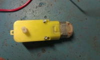
gearmotor, smooth side with m3 bolts
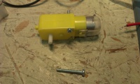
gearmotor, side view
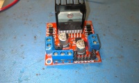
cheap L298N motor driver board (eBay)
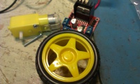
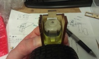
wheel, gearmotor, driver
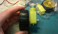
wheel mounted on gearmotor
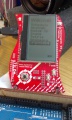
TiLDA


- Getting to grips with development on TiLDA: see EMF wiki for the most part (https://wiki.emfcamp.org/wiki/TiLDA_MKe)
- https://github.com/emfcamp/Mk2-Firmware
- MPU-6050
- MPU = Motion Processing Unit
- compare TiLDA usage with that of Sparkfun breakout schematic at https://cdn.sparkfun.com/datasheets/Sensors/IMU/Triple_Axis_Accelerometer-Gyro_Breakout_-_MPU-6050_v12.pdf
- orientation of the device and mapping to "normal" badge orientation
- libs... TODO
- Cheap little motors: almost ubiquitous little gearmotors with wheels £4.30 from China on eBay
- 2Pcs Smart Car Robot Plastic Tire Wheel with DC Biaxial Gear Motor for Arduino http://cgi.ebay.co.uk/ws/eBayISAPI.dll?ViewItemVersion&item=271534358812&view=all&tid=1348546156017
- Model : HC02-48, Working voltage: 3-6V, Specification: Biaxial, Reduction ratio: 1:48, 3V no load: 125 R/M, 3 V no load with 66 mm wheel: 26 m/min, 5 V no lode: 208 R/M, 5 V nolode with 66 mm wheel: 44 m/min, Torque: 0.8 kg/cm, Speed: fast
- Cheap motor drivers: ubiquitous L298N module
- Battery power: separate power supply from rechargeable AA batteries direct to motor driver.
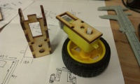
prototype body
- Laser cut (naturally!) from 3mm ply. Acrylic may be a bit brittle for the crashing that will occur!
- box out the motors as "legs" and form pegs to connect those to a smallish horizontal platform
- the motor driver can dangle below the platform, twixt the legs to "catch the breeze"!
- the TiLDA will be mounted above the platform in a variety of orientations configurable in the software
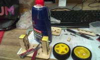
laser leg development - cutouts for bits
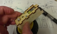
leg 3-sided box
wraps around gearmotor body and bolts on
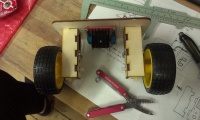
platform designed - dry fit
glue up
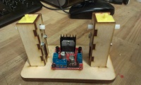
with motor driver board
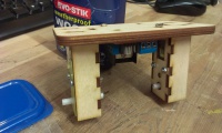
upright


prototype software
- choose how much of the emfcampbadge software to integrate
- e.g. do we want to just add RTOS tasks to the existing badge software?
- the display driver and menu system would be handy
- basic PID (proportional-integral-derivative) controller - see http://en.wikipedia.org/wiki/PID_controller
- existing instructable using MPU6050: http://www.instructables.com/id/Balancing-Instructable-Robot/
Stretch Goals
- Ball balancing: http://youtu.be/dr5xdpLL58A
- Total Segway domination - human or multi-human carrying!
- wheel-less eerie ball/egg