Difference between revisions of "ATMEGA32U4"
m |
(d) |
||
| (7 intermediate revisions by 3 users not shown) | |||
| Line 1: | Line 1: | ||
| + | {{project|status=In Progress|primary=[[User:Msemtd|Michael Erskine]]|type=member|}} | ||
Many hackers wish to produce a USB device that presents itself as a HID joypad, keyboard, or mouse to a PC or Pi to provide interesting interactions and I/O opportunities in a "standardised" manner. The Arduino Micro and more recently the Leonardo use a micro with an inbuilt USB peripheral device that can be repurposed directly. Previously the Arduino boards used a second small micro or dedicated USB chip (essentially another micro) to perform the USB-serial task but the cost of this additional device was high (often more than the micro itself) and that essential USB device feature soon found itself integrated into a number of Atmel chips. This was an opportunity for the Arduino project to divorce itself from a massive dependence on FTDI (in good time for [https://www.google.co.uk/search?q=%23FTDIGATE #FTDIGATE] !!) and for hackers to get involved with the delights of the at90usb82, atmega16u2, etc. as secondary processors for USB comms. | Many hackers wish to produce a USB device that presents itself as a HID joypad, keyboard, or mouse to a PC or Pi to provide interesting interactions and I/O opportunities in a "standardised" manner. The Arduino Micro and more recently the Leonardo use a micro with an inbuilt USB peripheral device that can be repurposed directly. Previously the Arduino boards used a second small micro or dedicated USB chip (essentially another micro) to perform the USB-serial task but the cost of this additional device was high (often more than the micro itself) and that essential USB device feature soon found itself integrated into a number of Atmel chips. This was an opportunity for the Arduino project to divorce itself from a massive dependence on FTDI (in good time for [https://www.google.co.uk/search?q=%23FTDIGATE #FTDIGATE] !!) and for hackers to get involved with the delights of the at90usb82, atmega16u2, etc. as secondary processors for USB comms. | ||
| Line 4: | Line 5: | ||
== Info Dump == | == Info Dump == | ||
| − | |||
* http://www.atmel.com/devices/atmega32u4.aspx | * http://www.atmel.com/devices/atmega32u4.aspx | ||
* full datasheet: http://www.atmel.com/Images/Atmel-7766-8-bit-AVR-ATmega16U4-32U4_Datasheet.pdf | * full datasheet: http://www.atmel.com/Images/Atmel-7766-8-bit-AVR-ATmega16U4-32U4_Datasheet.pdf | ||
| Line 435: | Line 435: | ||
I have taken delivery of another 10 boards at a cost of £2.35 each (including postage). --[[User:Msemtd|Michael Erskine]] ([[User talk:Msemtd|talk]]) 09:30, 4 September 2015 (UTC) | I have taken delivery of another 10 boards at a cost of £2.35 each (including postage). --[[User:Msemtd|Michael Erskine]] ([[User talk:Msemtd|talk]]) 09:30, 4 September 2015 (UTC) | ||
| − | These are the same technical specification and functionally equivalent however are slightly larger on a PCB of 23 x 40 mm | + | These are the same technical specification and functionally equivalent however are slightly larger on a PCB of 23 x 40 mm, the bigger ATMEGA32U4 package, and a Mini-USB socket rather than a Micro-USB socket. |
<gallery widths=500px heights=500px> | <gallery widths=500px heights=500px> | ||
File:Pro-micro-3-board-types.png|Genuine Arduino Micro, Pro Micro Large, Pro Micro | File:Pro-micro-3-board-types.png|Genuine Arduino Micro, Pro Micro Large, Pro Micro | ||
| + | File:Pro-micro-large-wired.png | Wired with 8x digital inputs on each side + GND | ||
| + | |||
</gallery> | </gallery> | ||
| + | |||
| + | == ProMicro Neopixel == | ||
| + | Code for neopixel test using simplest possible setup | ||
| + | <div style ="height:200px;overflow-x:hidden;overflow-y:auto;border: 4px solid green;"> | ||
| + | <syntaxhighlight lang="cpp" line="GESHI_FANCY_LINE_NUMBERS"> | ||
| + | #include <Adafruit_NeoPixel.h> | ||
| + | #ifdef __AVR__ | ||
| + | #include <avr/power.h> | ||
| + | #endif | ||
| + | |||
| + | #define PIN 21 | ||
| + | #define NUMPIXELS 1 | ||
| + | Adafruit_NeoPixel pixels = Adafruit_NeoPixel(NUMPIXELS, PIN, NEO_GRB + NEO_KHZ800); | ||
| + | |||
| + | // TODO serial comms not interfering with the pixel timing at all | ||
| + | // allow commands to set brightness as hex value 00 - FF | ||
| + | // allow commands to set colour as RGB hex value 000000 - FFFFFF | ||
| + | // flashing? | ||
| + | |||
| + | void setup() { | ||
| + | pixels.begin(); | ||
| + | } | ||
| + | |||
| + | |||
| + | |||
| + | void loop() { | ||
| + | pixels.setBrightness(10); | ||
| + | for(int i=0;i<NUMPIXELS;i++){ | ||
| + | pixels.setPixelColor(i, pixels.Color(10,10,10)); | ||
| + | pixels.show(); | ||
| + | delay(1000); | ||
| + | pixels.setPixelColor(i, pixels.Color(0,0,0)); | ||
| + | pixels.show(); | ||
| + | delay(500); | ||
| + | } | ||
| + | rainbow(25); | ||
| + | } | ||
| + | |||
| + | void rainbow(uint8_t wait) { | ||
| + | uint16_t i, j; | ||
| + | for(j=0; j<256; j++) { | ||
| + | for(i=0; i<pixels.numPixels(); i++) { | ||
| + | pixels.setPixelColor(i, Wheel((i+j) & 255)); | ||
| + | } | ||
| + | pixels.show(); | ||
| + | delay(wait); | ||
| + | } | ||
| + | } | ||
| + | |||
| + | // Input a value 0 to 255 to get a color value. | ||
| + | // The colours are a transition r - g - b - back to r. | ||
| + | uint32_t Wheel(byte WheelPos) { | ||
| + | WheelPos = 255 - WheelPos; | ||
| + | if(WheelPos < 85) { | ||
| + | return pixels.Color(255 - WheelPos * 3, 0, WheelPos * 3); | ||
| + | } | ||
| + | if(WheelPos < 170) { | ||
| + | WheelPos -= 85; | ||
| + | return pixels.Color(0, WheelPos * 3, 255 - WheelPos * 3); | ||
| + | } | ||
| + | WheelPos -= 170; | ||
| + | return pixels.Color(WheelPos * 3, 255 - WheelPos * 3, 0); | ||
| + | } | ||
| + | |||
| + | </syntaxhighlight> | ||
| + | </div> | ||
| + | |||
| + | [[Category:Arduino]] | ||
| + | [[Category:Projects]] | ||
Latest revision as of 16:07, 7 February 2019
| ATMEGA32U4 | |
|---|---|
| Primary Contact | Michael Erskine |
| Status | In Progress |
| Type | Members Project |
| QR code | |
Many hackers wish to produce a USB device that presents itself as a HID joypad, keyboard, or mouse to a PC or Pi to provide interesting interactions and I/O opportunities in a "standardised" manner. The Arduino Micro and more recently the Leonardo use a micro with an inbuilt USB peripheral device that can be repurposed directly. Previously the Arduino boards used a second small micro or dedicated USB chip (essentially another micro) to perform the USB-serial task but the cost of this additional device was high (often more than the micro itself) and that essential USB device feature soon found itself integrated into a number of Atmel chips. This was an opportunity for the Arduino project to divorce itself from a massive dependence on FTDI (in good time for #FTDIGATE !!) and for hackers to get involved with the delights of the at90usb82, atmega16u2, etc. as secondary processors for USB comms.
Time rolls on and the excitement of the brilliant but non-open Minimus project dies down to find a number of crazy-cheap options where the USB chip is the main chip. The Atmega32U4 can be found on the Arduino Micro (currently for about £20) but also on the wonderful Teensy 2.0 and some really cheap little "Pro Micro" boards from China that at £4 each are cheaper than buying just the chip from here in the UK (in reasonable quantities). Myself (Michael E) and Spencer have ordered some of these bonkers-cheap units for initial testing and evaluation. They would appear to be clones of the Sparkfun Pro Micro https://www.sparkfun.com/products/12640
Info Dump
- http://www.atmel.com/devices/atmega32u4.aspx
- full datasheet: http://www.atmel.com/Images/Atmel-7766-8-bit-AVR-ATmega16U4-32U4_Datasheet.pdf
- short summary: http://www.atmel.com/Images/Atmel-7766-8-bit-AVR-ATmega16U4-32U4_Summary.pdf
- DELIVERY 1: 10x board for £40: http://www.ebay.co.uk/itm/10x-Arduino-Pro-Micro-Leonardo-compatible-ATMEGA-32U4-5v-NEW-TESTED-UK-Stock-/161766720163?ssPageName=ADME:L:OU:GB:3160
- 1x board for £6
- 1x board - possibly even better (see fixes in description - to be compared with our delivery) http://www.ebay.co.uk/itm/Leonardo-Pro-Micro-ATmega32U4-16MHz-5V-Replace-ATmega328-Module-for-Arduino-Nano-/331611815908?hash=item4d359abfe4
Initial Works for DELIVERY 1
- board inspection: -
- what is included other than the MCU and a 16MHz crystal?
- what is missing other than the ICSP header?
- programming the board as an Arduino with Arduino IDE
- programming with dfu-programmer and avr-gcc, avr-libc, etc.
- what bootloader is provided? The Teensy 2.0 HALFKAY?
Chip markings (from ebay photos until we receive our first delivery)
   ATMEL
   MEGA32U4
   -MU
   1448E    TH
   A2N7XA
Initial risks and mitigations: -
- not a real ATMEL chip or bad batch/revision
- closer inspection of chip markings and initial firmware tests
- check JTAG IDs and Device Identification Register (26.3.2 in datasheet)
- bad oscillator circuitry or configuration
- pinout mapping for Arduino/teensy/Micro
    J1  |USBu|
   TX0          RAW
   RX1          GND
   GND          RST
   GND          VCC
     2          A3
     3          A2
     4          A1
     5          A0
     6          15
     7          14
     8          16
     9          10
  +----------------+
Michael's USB-HID Work
Origins: -
- Minimus
- LUFA
- Teensy and Teensyduino - holy grail! Configurable joysticks in Arduino IDE http://www.pjrc.com/teensy/td_joystick.html
- KADE
- UnoJoy
- https://learn.sparkfun.com/tutorials/pro-micro--fio-v3-hookup-guide
- followed and uploaded the onboard LED driving code - works well!
- now to create additional USB HID capabilities in the board definition
- https://github.com/sparkfun/SF32u4_boards
New project - very similar...
Test for ProMicro with 8 inputs and keyboard output: -
- HID descriptor help http://www.usb.org/developers/hidpage#HID Descriptor Tool
Test for ProMicro with 8 inputs, debounce, multitasking and serial output: -
Test for ProMicro with USB HID joystick, 8 inputs, debounce, multitasking and serial output (NB: needs mods to Arduino core USBAPI.h and HID.cpp in \arduino-1.6.5-r2\hardware\arduino\avr\cores\arduino): -
Success!!!!
I now have the holy grail of full Arduino IDE and APIs for with HID joypad on the Pro Micro clone - all working and tested. --Michael Erskine (talk) 15:38, 28 August 2015 (UTC)
Joypad code now on Github
The USB HID Joypad code is now in Github.
https://github.com/msemtd/promicro-joypad
You will need to edit some of the USB HID files in the Arduino core of 1.6.5 (ask for details). In time I should probably create a completely separate board profile but that's a lot of work! --Michael Erskine (talk) 09:42, 1 September 2015 (UTC)
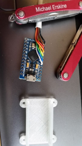
Wired into Defender Control Panel
Direct soldering to 8-way Alarm cable x 2 + 1 GND wire and mounted in Spencer's tiny 3D printed case. Replaces a USB dancemat controller that I was never 100% happy with!
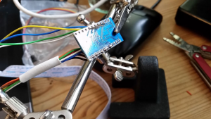
Direct soldering
Half-wired
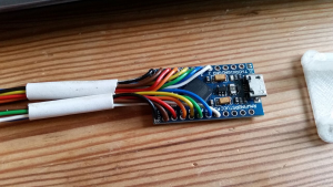
all digital inputs
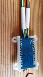
in 3D printed case
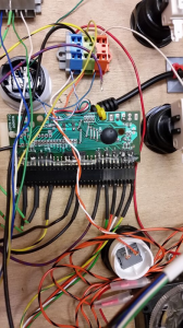
Replacing this mess


Large-style Pro Micro board
I have taken delivery of another 10 boards at a cost of £2.35 each (including postage). --Michael Erskine (talk) 09:30, 4 September 2015 (UTC)
These are the same technical specification and functionally equivalent however are slightly larger on a PCB of 23 x 40 mm, the bigger ATMEGA32U4 package, and a Mini-USB socket rather than a Micro-USB socket.
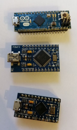
Genuine Arduino Micro, Pro Micro Large, Pro Micro
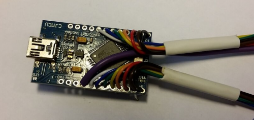
Wired with 8x digital inputs on each side + GND


ProMicro Neopixel
Code for neopixel test using simplest possible setup