Difference between revisions of "Aluminium Makercoin Trial"
m |
|||
| Line 28: | Line 28: | ||
==Manufacture== | ==Manufacture== | ||
I used [[Fusion 360]] to program the toolpath. | I used [[Fusion 360]] to program the toolpath. | ||
| − | + | ||
===Test cut=== | ===Test cut=== | ||
I used some laser cutter scrap to cut a wooden coin to test the size. This was cut using a 2mm ball nose bit. | I used some laser cutter scrap to cut a wooden coin to test the size. This was cut using a 2mm ball nose bit. | ||
| + | {| | ||
| + | ! {{#widget:YouTube|id=cyrvxYeEmlo|width=196|height=350}} | ||
| + | ! <gallery mode=packed heights=300px> | ||
| + | File:DanS makercoin testcut.jpg|Wooden trial run to test the depth of the embossing out. | ||
| + | File:DanS makercoin testcut2.jpg|Wooden trial run to test the depth of the embossing out. | ||
| + | File:DanS makercoin testcut3.jpg|Wooden trial run to test the depth of the embossing out. | ||
| + | </gallery> | ||
| + | |} | ||
| + | |||
| + | ===Final Version=== | ||
| + | For the first side, I used an adaptive toolpath with a 6mm tool to remove the majority of the material before switching to the 0.2mm Tapered bit. | ||
| + | |||
| + | I was so impressed with how the tapered bit worked that I didn't bother with the roughing cut on the second side. Worked well! | ||
| + | |||
| + | <gallery mode=packed heights=300px> | ||
| + | File:DanS makercoin Cut Settings Parallel.png|Toolpath settings for the Parallel cut | ||
| + | File:DanS makercoin Tool Settings1.png|Tool Parameters | ||
| + | </gallery> | ||
| − | |||
{{clear}} | {{clear}} | ||
===Cutting the real thing=== | ===Cutting the real thing=== | ||
| + | To do the flip part of the 2-sided milling I used two bolts. The idea was that the bolts would remain clamped to the bed between the two sides. Unfortunately it didn't quite work as one of the bolts loosened and moved as I undid the top nut. This meant that the second side of the coin was slightly offset against the first. | ||
| + | |||
| + | The next time I do this I will have a 3D Printed fixture that will remain clamped to the bed between the two OPs and hopefully get around this problem. | ||
| + | |||
| + | |||
<gallery mode=packed heights=250px> | <gallery mode=packed heights=250px> | ||
File:DanS makercoin 1.jpg|Cutting one side | File:DanS makercoin 1.jpg|Cutting one side | ||
Revision as of 21:56, 7 June 2019
| Aluminium Makercoin | |
|---|---|
 | |
| Primary Contact | Danspencer101 |
| Created | 04/06/2019 |
| Completed | 04/06/2019 |
| Status | Complete |
| Type | Members Project |
| QR code | |
I wanted to have a go at making a maker coin just for fun. The coin has a topographic map of the UK on one side and a 3D scan of my head on the other. Many makercoins that I've seen on YouTube are 3D printed but I wanted to have a go at CNC milling one.
This project is my first foray into flip milling (2 sided milling) so I'm not expecting it to be perfect.
Design

I used a few different programs to put this model together.
The first was Skanect which I used to take a 3D scan of my head. The second is a website called Terrain2Stl which I used to get the depth map of the UK. I also used some software called Meshmixer to tidy both the head scan and the map and scale them to approximately the right dimensions.
The coin itself was put together in Fusion 360. I was able to design the main coin body and then import & place the STL files in the required positions
Manufacture
I used Fusion 360 to program the toolpath.
Test cut
I used some laser cutter scrap to cut a wooden coin to test the size. This was cut using a 2mm ball nose bit.
|
|---|


Final Version
For the first side, I used an adaptive toolpath with a 6mm tool to remove the majority of the material before switching to the 0.2mm Tapered bit.
I was so impressed with how the tapered bit worked that I didn't bother with the roughing cut on the second side. Worked well!
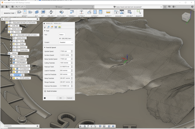
Toolpath settings for the Parallel cut
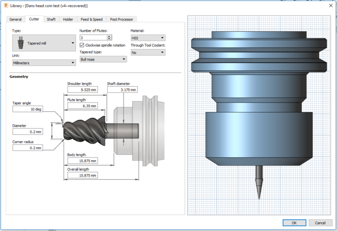
Tool Parameters


Cutting the real thing
To do the flip part of the 2-sided milling I used two bolts. The idea was that the bolts would remain clamped to the bed between the two sides. Unfortunately it didn't quite work as one of the bolts loosened and moved as I undid the top nut. This meant that the second side of the coin was slightly offset against the first.
The next time I do this I will have a 3D Printed fixture that will remain clamped to the bed between the two OPs and hopefully get around this problem.
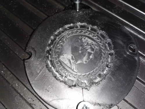
Cutting one side
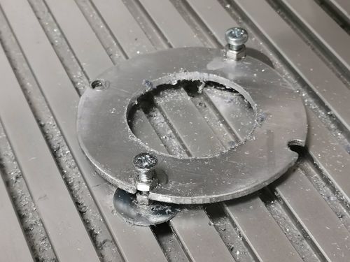
How the workpiece was clamped
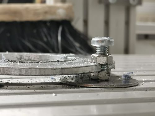
'Clamping post' arrangement
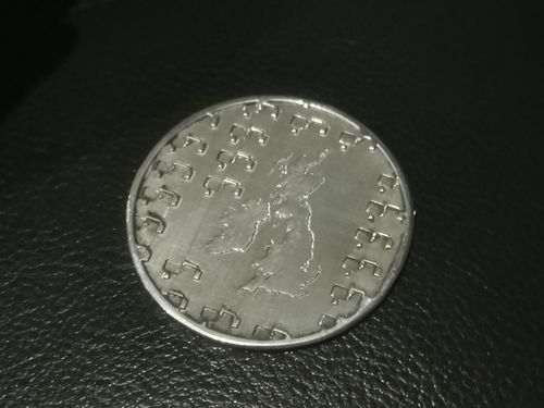
Map Side
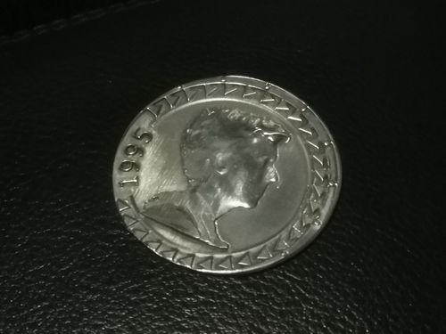
Head Side


