ESAB MIG Welder
MIG (Metal Inert Gas) welding (also known as GMAW - Gas Metal Arc Welding) uses wire fed through a welding 'gun' or 'torch'. The arc is struck between the wire and the workpiece, and shielded by an inert gas pumped through the torch. For more information or an introduction to MIG welding, see the references at the bottom of this page.
Our MIG welder is an ESAB LAW 500W witha separate wire feeder. The feeder is an ESAB MEK 4. The mig torch is a 400 amp water cooled Binzel model.
Current Status
It has been tested, and it welds very nicely. However, the earth lead needs work (underway at the moment), and the feed rollers and contact tip need replacing. The feed roller mechanism needs some tuning.
Power Supply
Currently shares a 32A 415V socket with the SMAW (stick) welder. A separate socket will be installed soon.
Quick Tour
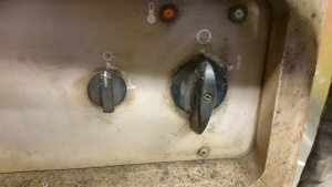
| This is the power switch (the larger one on the right) and the switch for the water cooling pump (the smaller one on the left).Running the water cooling pump without a torch attached will damage the pump. The pump needs to be able to circulate through something. | |
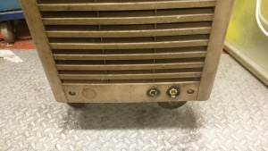
| These are the two work lead sockets. The right hand one has higher inductance than the left. | |
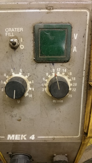
| This is the wire feed unit. At the back are connections for the welding current, water cooling, shielding gas and communications cable. On the front are connections for the mig torch (a euro style connector and two water cooling couplings) and for a remote control. There are two control knobs and a display. The left hand knob sets the welding voltage. The actual voltage used during the last weld will be displayed during the weld and after you finish. The right hand knob sets the wire feed speed. The switch is for 'crater fill' - this makes the machine taper off when you stop welding to try and avoid leaving a crater at the end of the weld. | |
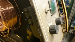
| Inside the panel on the left are 3 more controls. The top is the 2T/4T switch. In 2T mode, you have to keep the trigger on the torch held down while welding. In 4T mode, you press and release the trigger once to start welding and again to stop. Please leave this in the 2T position. The top potentiometer controls crater fill and the bottom one burn back - these should not normally need adjusting. | |
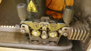
| This is the feed mechanism that pushes the wire through to the torch. The correct rollers need to be fitted for the size and type of wire in use. To release the rollers, move the two black cylinders (feed tension springs) apart and the rollers will lift up. You should not need to touch this unless you either have a wire jam, or you are changing the wire. | |
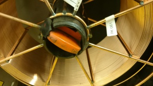
| This is the wire spool and brake hub. To remove the wire spool, rotate the red switch in the middle 90° and squeeze the two catches together. After installing a spool, rotate it back to lock the catches. |
Voltage Settings
This is a rough guide to settings - please correct or improve it if you discover something new.
| Dial Setting | Voltage Reported |
|---|---|
| 1 | 12.5V |
| 2 | 14.5V |
| 3 | 16.5V |
| 4 | 20.0V |
| 5 | 25.0V |
| 6 | 30.0V |
| 7 | 37.0V |
| 8 | 45.0V |
Manuals
LAW 500 Power Source (esab.com)
Useful References
A brief introduction from Miller - Mig Handbook (millerwelds.com)
A more comprehensive guide from Lincoln Electric - GMAW Guide (lincolnelectric.com)
Video introduction to MIG welding (weldingtipsandtricks) - Mig Welding Basics (youtube.com)
Guide to welding filler metals - Basic Welding Filler Metal Technology Correspondence Course (esab.com)
