Difference between revisions of "Inkscape"
(forums) |
(→Resources: not used) |
||
| Line 245: | Line 245: | ||
* [https://inkscape.org/en/doc/keys091.html Inkscape keys and mouse reference (v0.91, inkscape.org)] | * [https://inkscape.org/en/doc/keys091.html Inkscape keys and mouse reference (v0.91, inkscape.org)] | ||
* [http://www.inkscapeforum.com/index.php Inkscape forum] | * [http://www.inkscapeforum.com/index.php Inkscape forum] | ||
| − | |||
* [https://www.reddit.com/r/Inkscape/ Inkscape Reddit] | * [https://www.reddit.com/r/Inkscape/ Inkscape Reddit] | ||
Latest revision as of 10:39, 22 July 2019
| Inkscape | |
|---|---|
| |
| Developer | The Inkscape Project |
| Uses | 2D vector graphics design |
| Operating System | Windows, macOS, GNU/Linux and FreeBSD |
| Native format/s | SVG |
| Other format/s | DXF |
| License | GPLv3+3 |
| inkscape.org | |
| Software: all pages {{}} | |
Inkscape is a brilliant free and open-source software program for creating 2D vector graphics. It can be used for creating designs for the laser cutter (by exporting to DXF).
Installation
The download page shows you the installer files for your operating system. Note, for a slight increase of speed for complex files on 64bit systems use the Partha builds.
Setup
Geometric Bounding Box
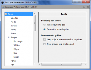
Inkscape is by default set up for outputting to the screen or to a printer rather than as a CAD tool for engineering, and so the bounding boxes for objects include the thickness of the line strokes. Whilst this is also true for the kerf of our laser cut designs we usually want to be able to enter exact measurements for the bounding box sizes of objects that are based on the centres of the line strokes, the thickness of which is irrelevant when imported to LaserCut. To set this behaviour go to the Inkscape Preferences (File -> Inkscape Preferences), under the Tools section select Geometric bounding box.
Grid Setup
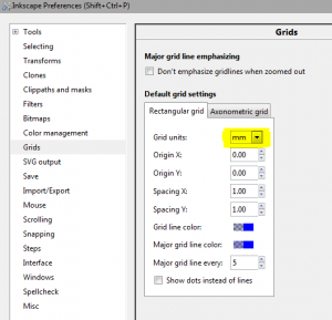
Inkscape by default works in pixels as the measurement; for the grids and page size. First of all to change the grids go to the Inkscape Preferences (File -> Inkscape Preferences), under the Grid section select "mm" instead of the default "px". This affects all new files, so select File -> New to open one, and go to View -> Grid to see it in action.
In addition it may be useful to have the snapping turned on for Snap to cusp nodes on the right hand side. What this will do is allow the nodes you've created (such as corners) to snap to the MM grid for more precise tuning.
Usually you'll want your actual lines you're drawing to be reasonably thick to be able to see them more easily over the grid. The lines won't have any thickness on export to LaserCut; and will appear thin. The line thickness in Inkscape is set in the third tab of the Fill and Stroke dialogue box, (shortcut Ctrl + Shift + F).
It is also worth consider major line spacing. Inkscape will not show the minor grid line unless the user is sufficiently zoomed in.
Document Settings and Templates
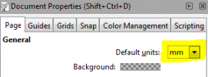
By default Inkscapes default file will be in pixels with an A4 portrait size. The easiest option to create one using millimetres is to select A4 Landscape from the New menu. You can also change a documents units setting any time under File -> Document Properties and selecting mm instead of px for the Default units.
You may also be interested in templates for various sizes of material. If you save these to your Inkscape templates folder (under Windows: %appdata%\inkscape\templates, under Linux ~/.config/inkscape/templates ) you can select them from the New menu. If you want to replace the default, rename one of them to "default.svg". This can save a lot of time when creating multiple items! These are all landscape, but you can save whatever basic SVG you want as a new template.
- Laser A4 template (Landscape, 297x210mm)
- Laser A3 template (Landscape, 420x297mm)
- Laser A2 template (Landscape, 594x420mm)
- Laser A1 template (Landscape, 841x594mm)
- Laser A0 template (Landscape, 1189x841mm)
- Laser 1200x900mm template (Landscape) - A0 isn't quite full bed size - note cutting area of the laser is not necessarily to each edge. This template might be required to line up large materials however.
Once your document is set to MM it will import accurately into Laser Cut 5.3.
Usage Tips
Some tips for usage, a full tutorial may come later:
Coloured Paths
Some of the Inkscape colours are exported with the DXF which can be used to mark areas for engraving, different powers or even different orders of cut. Make sure to have the colours match across everything of one type.
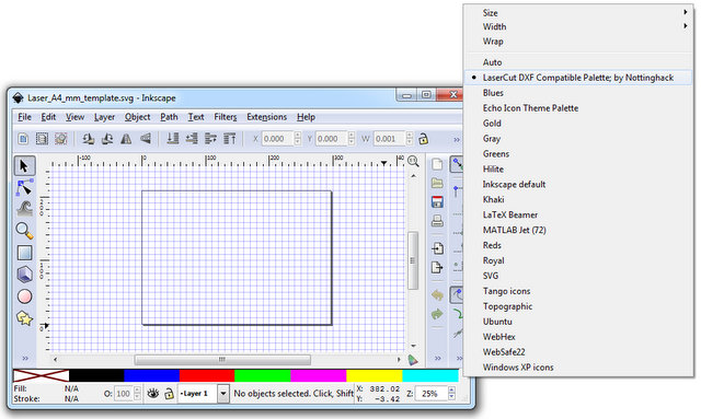
Due to the limited DXF colour export (it only does the 7 primary RGB colours) you can use our custom palette for Inkscape.
Generally it is easier to colour engravings as something special, eg:
- Black - cuts
- Blue - engraving areas
- Green - engraving-power cuts
- Others - other things
See the tutorials on LaserCut for how to use this powerful feature.
These colours are:
| Colour | Red Value (R) | Green Value (G) | Blue Value (B) |
|---|---|---|---|
| Black | 0 | 0 | 0 |
| Red | 255 | 0 | 0 |
| Green | 0 | 255 | 0 |
| Blue | 0 | 0 | 255 |
| Yellow | 255 | 255 | 0 |
| Magenta | 255 | 0 | 255 |
| Cyan | 0 | 255 | 255 |
Extra Colours?
There are also alternative ways of converting SVG to DXF that may retain more colours (the Inkscape DXF plugin might be losing some colours in the conversion process that are actually supported by the DXF format). We also have a complete LaserCut palette file which might be useful for this (although it is untested; some of them do not match the AutoCAD DXF colour palette).
Area fills and Layers
You can fill-colour in areas (eg; to show engraving areas) which makes things easier to see, and use layers and transparency to show/hide or overlay different areas. These are all collapsed or ignored when exporting to DXF, which is useful.
Area fill colour also helps determine if a path you've created is really a completed one. A good engrave area is a fully contiguous single line which is joined up to itself, although the DXF export splits the continuous line into one line with two end points which is easily fixed in Laser Cut.
Paths only!
When finishing a file ready to export select the entire document and go to Path -> Object to Path. The only thing a laser understands is paths (lines) and this may catch any you missed if converting an image file over; objects are not supported.
Leave mess in
You can leave in the SVG embedded images (eg; jpegs you are tracing) and the DXF file will simply exclude them when it is created. You can check the import in the Laser Cut demo or by opening the DXF file again with Inkscape.
Colour by Layer
After selecting an object or path you can use the right click menu to "Select same" and then choose the "Stroke colour".
Then you can right click (one of the selected items) and choose "Move to layer" to select an appropriate layer.
All selected items will be moved to the corresponding layer, making it easier to separate out the different colours for logically separating out different engrave, fast-cut or cut settings.
Layering Order
LaserCut reverses the order of the layers when it imports a DXF file. NOTE: This effect doesn't seem to occur when the "Save a Copy" option is used to generate a DXF. It seems to consistantly apply if the "Save as" option is used to generate a DXF. Be aware that this changes the current open file in Inkscape to the DXF version, so any changes made will not automatically be added to the SVG version (Inkscape will prompt you to save as SVG when you close the file).
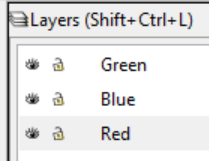
So, if you have the following layers set up in Inkscape, with each coloured stroke assigned to it's appropriate layer, when you save the drawing to a SVG:
They will be reversed to this order in LaserCut:
This can be useful to "pre-set" the engrave, fast-cut and cut layers for importing; especially when using the full 7 colours that LaserCut supports importing from a DXF (mentioned above).
Z Order (Stacking within a layer)
The stacking order of items inside a layer does seem to have an impact on the cutting line determined by LaserCut. In the same manner that the Layer Order is reversed, it appears the top most path is the most likely to be cut first. This seems to depend on how many changes the "Unite Lines" tool needs to make and more testing is required to provide definitive results.
Overlapping Lines
If cutting two objects that share a common line (e.g. two squares side by side) it's possible to remove one of the overlapped lines using the "Edit Nodes" tool in Inkscape. This prevents the Laser Cutter from tracing and cutting the same line twice, and is a little bit more efficient (or a lot more, depending on how many overlapping lines there are).
It may be a good idea to remove these overlapping lines in the DXF copy of your file so any movements or changes in the SVG in future will not need lines to be re-added.
Engraving
The Laser can only engrave on the (longer) X axis and moves by the "scan gap" in the (shorter) Y axis.
Therefore, when engraving it's more efficient to orientate the objects being engraved to match the X axis of the Laser Cutter as much as possible.
It is also possible to group items with different coloured lines in order to force the Laser to engrave particular items in a particular order as set by the layering in LaserCut. This is, anecdotally, quicker when there are several items spread along the whole X axis of the piece being engraved with large gaps in the middle as the Laser head doesn't need to move quite as far on the X axis before moving on the Y axis ("scan gap").
Test Cut File
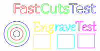
This file can be used by any member of the Hackspace to quickly run several different engrave, fast-cut or cut settings. The text used is just a placeholder, any settings can be used (i.e. The colours used to spell "Fast Cut Test" do not have to be used for testing fast cuts).
The total area used by this file as-is (and once imported in to LaserCut sections can safely be deleted) are approximately 75mm wide by 40mm tall.
Extensions
Extensions to Inkscape allow you to use tools other people have made to create good laser-compatible items. Copy extension files to this folder and restart to activate:
- Windows: %appdata%\inkscape\extensions (note: %appdata% typically refers to \Users\<your-username>\AppData\Roaming)
- OS X & Linux: ~/.config/inkscape/extensions (note: ~ refers to the user's home directory, typically /home/<your-username> on Linux or /Users/<your-username> on OS X)
Custom Colour Palette
We have created a custom colour palette which contains only the colours which survive the DXF export from Inkscape (both the DXF format and LaserCut support only a very limited number of colours). It can be found in the LaserCut Installation Files at \Nottinghack LaserCut\Inkscape Files\LaserCut_Laser_Palette.gpl. First ensure that you have installed Inkscape and then copy the LaserCut_Laser_Palette.gpl to the following location, depending on the platform:
- Windows: %appdata%\inkscape\palettes (note: %appdata% typically refers to \Users\<your-username>\AppData\Roaming)
- OS X & Linux: ~/.config/inkscape/palettes (note: ~ refers to the user's home directory, typically /home/<your-username> on Linux or /Users/<your-username> on OS X)
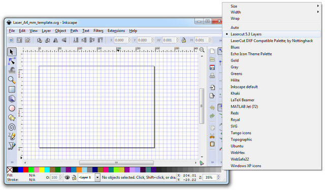
Once you have copied the palette into the correct location, restart Inkscape if you have it open and then click the small arrow to the far right of the bar of colours at the bottom of the screen. This should pop up a list of alternative palettes to use, you should see a new one what we just installed.
We also have a complete LaserCut palette file which contains all 39 of the colours in LaserCut 5.3 (there are actually 40 buttons but two are the same colour for some odd reason), only 7 of the colours in this palette will survive the DXF export, other formats may yield better result, please document any successes.
Hershey Font
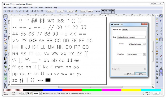
Hershey fonts are for engraving nicely on laser cutters. That page details how to install and use them. A mirror will be added here at some point.
Tabbed Box Maker
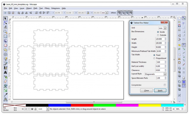
Boxes are a big thing for laser cutters. Everyone makes boxes. We love them. Tabbed Box Maker (broken) [1] (0.48) [2] (0.91) [3] (0.93) helps make nicely tabbed boxes of all kinds.
Tip:
- Use inside measurements to fit something in, and outside measurements to make the extremities of the box a specific size, based on the material thickness.
- Use millimetres and use the MM thickness of your wood the Material Thickness box (defaults to 3mm). This affects tab size and the inside versus outside size changes.
- The cut width of our laser tends to be around 0.1mm (which is the suggested default).
- The tab width defaults to 10.000 - so a reasonable 1cm. Put a larger value in for bigger (but fewer) tabs, useful on longer edges.
DXF file export settings
You must save what you want in the DXF file format. This format is not as reliable to re-edit so keeping the original SVG is recommended, use File -> Save As Copy to do an "export" to DXF:
The DXF file exports:
- Paths (lines created in your file)
- Colours of paths
It will exclude:
- Embedded images
- Layers
- Transparencies
- Fills
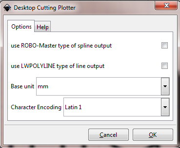
The save options can also help a bit. The main thing is it must be set to mm, and the tickboxes vary the output that is imported. The best default is no tickboxes since in both cases they can cause errors when importing into LaserCut! So use:
You can stop reading now; this section will probably be removed but is for information
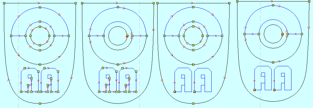
The two tickboxes affect how the different paths of the file are split on save. Below are images from LaserCut after importing with the various options.
From left to right:
- No tickboxes - all paths are split (note that this may allow the laser to determine the quickest cutting path better and most of the time is absolutely fine).
- ROBO-MASTER ticked - the splines (curved lines) are smoothed and kept linked - see the circle on this one is slightly "elongated" and not fully round!
- LWPOLYLINE ticked - the straight lines in the A's are not split anymore. In fact the A was created by a long use of the polygon tool in Inkscape and connected together at the end point and imported over perfectly. However later tests with more curved lettering shows it starts to miss out vital line vector points and the Unite tool in LaserCut goes awry.
- Both ticked - both the above occur. It isn't perfect due to the ROBO-MASTER setting making curves less curved however.
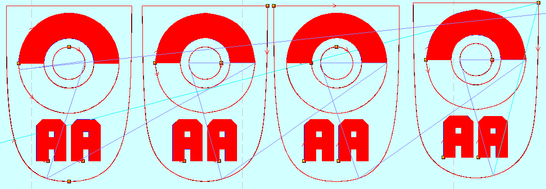
Note that in all cases the lines are not perfect (gaps where the splines and straights match up for instance). However after selecting the Tools -> Unite Lines option in Laser Cut provides pretty much the same cut (red line) and engrave (red area) for each one:
Note how the 2nd and 4th picture the circle is not precise!
The main thing to watch with this design was there are 2 cut lines at the bottom lines of the top engrave; these seem to have been united properly on all designs.
However more complex designs using same-colours for some overlapping lines may cause issues if the Unite Lines tool attaches the wrong nodes together (How does it determine what gets linked at a junction?), so the tickboxes would potentially solve some of these. Best bet is to use no tickboxes.
