Difference between revisions of "InterhackerspacePBX/Payphone"
Jump to navigation
Jump to search
m (Danspencer101 moved page Project:InterhackerspacePBX/Payphone to InterhackerspacePBX/Payphone) |
|||
| Line 120: | Line 120: | ||
[[Category:Projects]] | [[Category:Projects]] | ||
| + | [[Category:Payment]] | ||
Latest revision as of 13:55, 26 June 2019
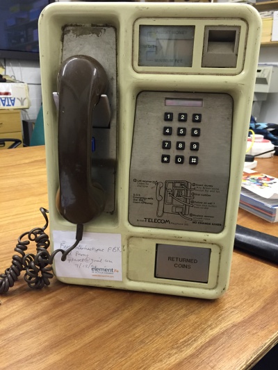
The Payphone is a British Telecom Payphone 300
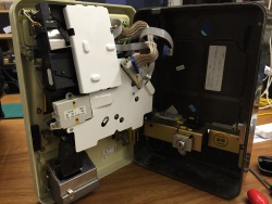
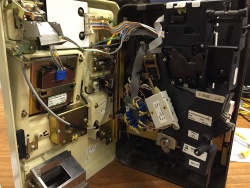
Internally its missing the main logic board and the cash box
Conversion Plan
Pi + usb audio and a sip softphone
Keypad
Its expected the keypad it a standard matrix style that we can connect directly to the pin or via a ATMega chip
LCD
LCD looks to be a 7 segment style, 4 digits
Connections
There are 4 connections internal details of the pins outs can be found below
Main connection 34 pin connector
| Pin | Colour | Function | Detail |
|---|---|---|---|
| 1 | Brown | LCD | |
| 2 | Red | LCD | |
| 3 | Orange | LCD | |
| 4 | Yellow | LCD | |
| 5 | Green | LCD | |
| 6 | Blue | LCD | |
| 7 | Purple | LCD | |
| 8 | Grey | LCD | |
| 9 | White | LCD | |
| 10 | Black | LCD | |
| 11 | Brown | LCD | |
| 12 | Red | LCD | |
| 13 | Orange | LCD | |
| 14 | Yellow | LCD | |
| 15 | green | Keypad | Row 3 (PL1) |
| 16 | Blue | Keypad | Col 2 (PL2) |
| 17 | Purple | Keypad | Row 0 (PL3) |
| 18 | Grey | Keypad | Col 1 (PL4) |
| 19 | White | Keypad | Row 1 (PL5) |
| 20 | Black | Keypad | Row 2 (PL6) |
| 21 | Brown | Keypad | Col 0 (PL7) |
| 22 | Red | Spare | N/C |
| 23 | Orange | Hook | |
| 24 | Yellow | Hook | |
| 25 | green | Follow | |
| 26 | Blue | Follow | |
| 27 | Purple | Speaker | |
| 28 | Grey | Speaker | Positive (I think 'RepRap' Matt) |
| 29 | White | Spare | N/C |
| 30 | Black | Spare | N/C |
| 31 | Brown | Spare | N/C |
| 32 | Red | Spare | N/C |
| 33 | Orange | Spare | N/C |
| 34 | Yellow | Spare | N/C |
The hook switch state is:
- Closed, On Hook
- Open, Off hook
Handset 5 pin connector
This connector is keyed, Pin 2 is blocked out
| Pin | Colour | Function | Detail |
|---|---|---|---|
| 1 | Red | Speaker | |
| 2 | N/A | Key | |
| 3 | Blue | Mic | |
| 4 | Green | Speaker | |
| 5 | White | Mic |
Coin accepter
10 pin TBD
Coin holder
14 pin TBD


