InterhackerspacePBX/Payphone
Jump to navigation
Jump to search
The printable version is no longer supported and may have rendering errors. Please update your browser bookmarks and please use the default browser print function instead.
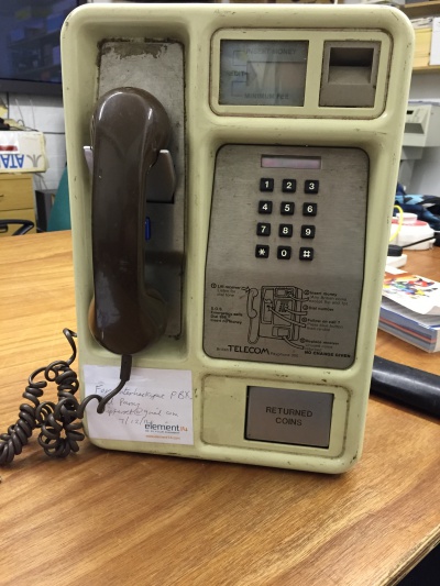
The Payphone is a British Telecom Payphone 300
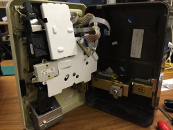
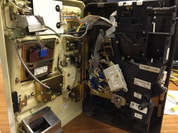
Internally its missing the main logic board and the cash box
Conversion Plan
Pi + usb audio and a sip softphone
Keypad
Its expected the keypad it a standard matrix style that we can connect directly to the pin or via a ATMega chip
LCD
LCD looks to be a 7 segment style, 4 digits
Connections
There are 4 connections internal details of the pins outs can be found below
Main connection 34 pin connector
| Pin | Colour | Function | Detail |
|---|---|---|---|
| 1 | Brown | LCD | |
| 2 | Red | LCD | |
| 3 | Orange | LCD | |
| 4 | Yellow | LCD | |
| 5 | Green | LCD | |
| 6 | Blue | LCD | |
| 7 | Purple | LCD | |
| 8 | Grey | LCD | |
| 9 | White | LCD | |
| 10 | Black | LCD | |
| 11 | Brown | LCD | |
| 12 | Red | LCD | |
| 13 | Orange | LCD | |
| 14 | Yellow | LCD | |
| 15 | green | Keypad | Row 3 (PL1) |
| 16 | Blue | Keypad | Col 2 (PL2) |
| 17 | Purple | Keypad | Row 0 (PL3) |
| 18 | Grey | Keypad | Col 1 (PL4) |
| 19 | White | Keypad | Row 1 (PL5) |
| 20 | Black | Keypad | Row 2 (PL6) |
| 21 | Brown | Keypad | Col 0 (PL7) |
| 22 | Red | Spare | N/C |
| 23 | Orange | Hook | |
| 24 | Yellow | Hook | |
| 25 | green | Follow | |
| 26 | Blue | Follow | |
| 27 | Purple | Speaker | |
| 28 | Grey | Speaker | Positive (I think 'RepRap' Matt) |
| 29 | White | Spare | N/C |
| 30 | Black | Spare | N/C |
| 31 | Brown | Spare | N/C |
| 32 | Red | Spare | N/C |
| 33 | Orange | Spare | N/C |
| 34 | Yellow | Spare | N/C |
The hook switch state is:
- Closed, On Hook
- Open, Off hook
Handset 5 pin connector
This connector is keyed, Pin 2 is blocked out
| Pin | Colour | Function | Detail |
|---|---|---|---|
| 1 | Red | Speaker | |
| 2 | N/A | Key | |
| 3 | Blue | Mic | |
| 4 | Green | Speaker | |
| 5 | White | Mic |
Coin accepter
10 pin TBD
Coin holder
14 pin TBD


