Difference between revisions of "Laser cutter/LaserCut/Usage"
(→Importing Files: +info on DXF) |
|||
| Line 20: | Line 20: | ||
These line file formats can be imported: | These line file formats can be imported: | ||
| − | * '''DXF - AutoCAD''' - this is our preferred method of import | + | * '''DXF - AutoCAD''' - this is our preferred method of import, with [[Laser cutter/Inkscape|Inkscape support]] (although with a limited colour palette) |
| − | * AI - Adobe Illustrator File - need to know what is imported | + | * AI - Adobe Illustrator File - ''need to know what is imported'' |
| − | * PLT - HPGL Plotter File - need to know what is imported, where this can be created from | + | * PLT - HPGL Plotter File - ''need to know what is imported, where this can be created from'' |
| − | * TST - Tajima - need to know what is imported, where this can be created from | + | * TST - Tajima - ''need to know what is imported, where this can be created from'' |
| − | * NC - Mastercam - need to know what is imported, where this can be created from | + | * NC - Mastercam - ''need to know what is imported, where this can be created from'' |
You can also import previously made ECP files by typing '''*.epc''' in the '''File Name:''' box and selecting '''Open''' - this will only import the lines and colours not the power settings or order, but is a reasonable way to save time if you wish to just get a completed design ready but don't have the original DXF or SVG. | You can also import previously made ECP files by typing '''*.epc''' in the '''File Name:''' box and selecting '''Open''' - this will only import the lines and colours not the power settings or order, but is a reasonable way to save time if you wish to just get a completed design ready but don't have the original DXF or SVG. | ||
| Line 30: | Line 30: | ||
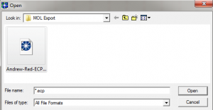
[[File:LaserCut-Import-ECP.PNG|thumbnail|none|Importing ECP files into LaserCut]] | [[File:LaserCut-Import-ECP.PNG|thumbnail|none|Importing ECP files into LaserCut]] | ||
| − | These image file formats can be imported: | + | These image file formats can be imported for engraving work: |
* BMP, JPG/JPEG, GIF, PNG, TIF/TIFF, TGA, PCX | * BMP, JPG/JPEG, GIF, PNG, TIF/TIFF, TGA, PCX | ||
Revision as of 10:23, 28 May 2014
This page will detail how to get the best out of LaserCut.
What is a cut versus and engrave?
The only difference of the two is that an engrave covers a bounded area with lots of small cuts. This means you can "engrave" lines into something using just cuts of a lower power.
Quirky Notes
NOTE: The demo software will crash in the demo on A0 "Silvertail" settings. Please change the file "syscfg - Silvertail.ini", find "NeedRevise=1" under section "[TWOAXIS_0]" and change it to "NeedRevise=0" - a revised download may be provided soon.
The software has some oddities - there are things hidden behind scroll bars and please note: the enter key never saves settings (in many cases) so you must click "Ok" to save things.
Also at the moment the word "Download" really should be "Upload".
The long-running tools (such as "Preview" and "Calculate time") have no cancel button but pressing escape seems to exit them fine.
Importing Files
LaserCut does not import direct SVG files; it requires more simple files to import. It can also work with images directly using them to direct engrave areas.
These line file formats can be imported:
- DXF - AutoCAD - this is our preferred method of import, with Inkscape support (although with a limited colour palette)
- AI - Adobe Illustrator File - need to know what is imported
- PLT - HPGL Plotter File - need to know what is imported, where this can be created from
- TST - Tajima - need to know what is imported, where this can be created from
- NC - Mastercam - need to know what is imported, where this can be created from
You can also import previously made ECP files by typing *.epc in the File Name: box and selecting Open - this will only import the lines and colours not the power settings or order, but is a reasonable way to save time if you wish to just get a completed design ready but don't have the original DXF or SVG.
These image file formats can be imported for engraving work:
- BMP, JPG/JPEG, GIF, PNG, TIF/TIFF, TGA, PCX
If the program continually crashes importing, first of all entirely restart the program, and possibly de-select "Preview" so it doesn't read the file (it can fail if the file is open by something else). Otherwise INI file has become corrupt (perhaps on a crash of the program). Copying the original again by running the bat file fixes this.
Saving files
Saving in the demo:
- Can save ECP files on exit or if selecting "New" from File menu. Press Yes on the dialogue box to
- Unite Lines are saved if ECP is imported again, but the laser cut/engrave/etc. settings for speed and power are lost
- This however is better then just leaving it as a DXF
- .MOL exports are the best "final" file but any adjustments means re-creating them - they can be rather large files even for simple designs!
Exporting MOL files
NOTE: Both the demo and normal program can export .MOL as long as you have not used the tool Data Check (under Tools -> Data Check) since this causes it to crash. To fix this either re-apply the default config file settings, or remove the line CheckLayerCode=-1 under [DataCheck].
Tiling / Multiplying objects
Select the option Set array output options from the toolbar. This will help create copies of an object which can be altered so they overlap nicely. It isn't a perfect way to tessellate an object (using one cut line for two objects for instance) but is good enough for non-tessellating objects to be multiplied for multiple copies quickly, and is a lot easier than using Inkscape to do the same thing.
Colours
You can use multiple colours in a design to separate different types of action; for instance a good practice may be to have:
- Black - All cut lines
- Blue - engrave areas
- Green - engrave (low power) lines (cut option at a lower power).
- Red and other colours - other engrave areas/lines
If this method is used it can be easy to import a DXF file which has the correct layers already set up.
However there are limitations:
- DXF export is limited to the AutoCAD Color Index (ACI).
- DXF import into LaserCut is limited to the odd selection of colours at the bottom.
These do not match up; therefore for Inkscape we will create a simplified palette to use to import the correct (AutoCAD reliable) colours into LaserCut. The basic RGB Black, Red, Green and Blue all work however.
Machine Settings
Simply put: please don't change any settings under File -> Machine-Options since the given settings are for the A0 laser we have, and incorrect settings can break the laser.
Types of Cut
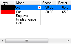
You can set different coloured items to do different things - such as having one set of cut lines cut though, while another set of cut lines only engraves at a lower power. These are the dropdown options on the layer selector:
Basic Settings
These are some recommended numbers to take into account:
Remember: Power and Speed affect the cuts/engraves equally; a slower cut of 30mm will cut through 3mm wood at 65% power, while 600mm at 65% power will only engrave the wood partially. Equally a higher power at the same speed will cut deeper.
Power:
- The laser cutter power is in percent.
- Usually you want to maximise the power used, so the speed can be increased to make the cut time shorter.
- Please limit upper power to 65%, especially since higher can make things burn.
- The lowest appreciable power appears to be around 12%, at slow speeds it can just about etch lightly some wood, but might be more applicable to paper cutting.
Speed:
- Speed affects the accuracy of cuts as well as the time they take - tiny 400mm cuts may be wonky for instance. Try lowering it to 300 or 200mm instead at a lower power to achieve the same effect.
- Engraving cuts can be as high as 1000mm, which is fine due to it being only on one axis of movement. It requires high power however to make any effect at this speed and may result in some bad engraving.
Overlapping areas
- Each line / area is done once, regardless of if it overlaps something else. The order of the colours may be important - cutting last is usually the best method to get a clean finish since if you cut first the item may drop/move when released from the surrounding material.
- The fact you can overlap areas of engrave or lines of cut means you can achieve multi-later engraves and cuts.
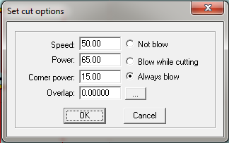
Cut
A cut is a single run of the laser at a set power along a desired line. This line can be at any angle, or in circular patterns.
This means you can either cut through a material or leave a thin engrave line the exact width of the laser; around 0.1mm size.
- Speed - Speed in millimetres the laser moves at. For cuts this is usually 50 or lower, for engraves 300 and higher. The maximum is 400 speed since cuts can go both on the X and Y axis at once.
- Power - Percentage power of laser. Do not use higher than 65%, this is unnecessary and will burn the laser out or potentially burn your material. For cuts 65 and altering the speed is usually best, and for engraves a power of 30-40 seems to be better.
- Corner power - It defaults to 15% but can be set to the used power, -10% or so (for 65% you could use 55% for instance). This is so it won't burn the corners since when the motors make it turn it will hold the laser in position for a little longer.
- Overlap - The manual states a badly calibrated laser can use this to cut better; for ours this is unnecessary. Leave it alone.
- ... - Advanced options, leave them alone, the defaults are fine.
Examples: to follow.
Engrave
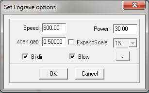
Engraving means the laser is moved over an area with a lower power or faster speed to allow the surface to be engraved with a pattern. There are further options to decide the gap between the scan lines which cover the area.
Note that any line you select for engrave which doesn't contain a contiguous area will still be engraved, just it will overlap with where the line is. Check the preview for how this looks.
- Speed - Speed in millimetres the laser moves at. Engraves can vary at speed, but 300 or higher is highly recommended (600 - 800 can work well). The maximum for engraves is a high 1000, which is because it is only going on the X axis means the upper limit is higher.
- Power - Percentage power of laser. Do not use higher than 65%, this is unnecessary and will burn the laser out or potentially burn your material. For cuts 65 and altering the speed is usually best, and for engraves a power of 30-40 seems to be better.
- Scan gap - The distance in millimeters between each line on this engrave area. This setting will vary by material - it can go very low. The laser should be around 0.1mm for the single point it fires, but make sure you experiment! Some reasonable defaults may be:
- 100DPI - 0.25
- 250DPI - 0.1
- 300DPI - 0.085
- ExpandScale - This will overscans or underscans the area that the shape is. This can be very useful to allow for the kind of thick lines something might be drawn in InkScape which you might not account for when it is imported into LaserCut. It will also helpfully affect single lines you've selected for engraving.
- Bi-dir - Does the laser do both left and right engraves? If unticked it will only do one direction (and be slower) but might be better for certain materials.
- Blow - Controls the air flow, always leave enabled.
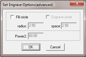
- ... - Advanced Engrave options:
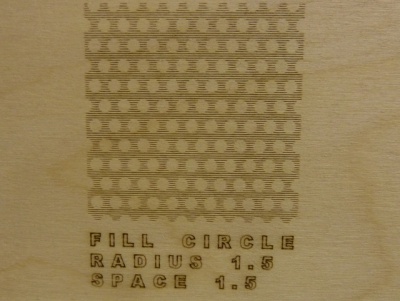
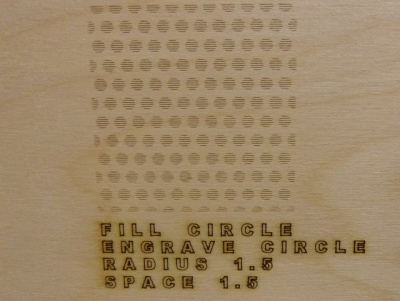
- Fill circle - Will allow the other options to be selected.
- Engrave circle - If off, it will engrave and leave circles un-engraved. If on, it will engrave just circles. Potentially this can be used to cut but is inefficient, possibly good for marking areas without engraving them entirely.
- Radius - Radius of the circle in MM
- Space - Space between circles in MM
- Power2 - Ignore, we don't have a second laser on our laser cutter, so it is diasbled.
Grade Engrave
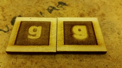
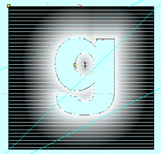
Grade Engrave will cause an area inside a engraved area to have raised edges. It is intended for easier rubber stamp making but can be applied to any real use. It is easiest to show with pictures:
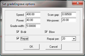
There are options for this similar to Engrave:
- Speed - Speed in mm of the engrave. Set to whatever speed at the deepest should be.
- Scan gap - The gap on the Y axis between scan lines. 0.08500 is similar to 300DPI. The laser cuts roughly slightly less then 1mm holes.
- Power - The baseline maximum power, used for areas not near text (black in the above example)
- Min-power - The minimum power, used nearest to the edge of the lettering, where it is whitest.
- Bi-dir - Should remain on usually, if turned off it will only cut on one direction pass of the laser, slowing it down.
- Blow - Should remain on, blows the air onto the area.
- Repair - A vague option; not tested fully. The manual states "select this option and the engraved letters will be clearer".
- Repair per - A vague option of a vague option; not tested fully. Defaults to 20. The manual states helpfully "change the parameter will adjust the definition of the engraved letters". Higher? lower? You guess!
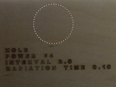
Hole
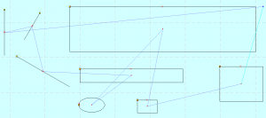
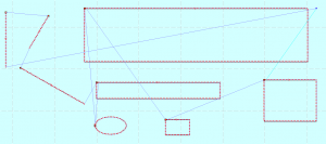
This may be useful for marking small areas or centres of objects and has two main options:
Hole on center
This puts a single laser cut at a specific power in the middle of all the selected objects. This could be useful for marking where things will end up, or for shapes like circles having the center marked (maybe after cutting and engraving it initially) for where attachments go. The output looks like this:
Holes on the lines
When Hole on center is not ticked, it will allow you to have single laser holes cut at intervals. This may be useful to put perforations in paper or card (although they may not work very well!) or for marking areas or having a different style of line engrave at lower powers. The output looks like this:
Note: Setting the interval too low (eg: 0.1) will essentially result in a cut which is made up of lots of holes and will result in a bad finish around the edges.
Pen Cut
This option is only in the Demo and does not appear in the final application. It crashes the Demo. Probably an oversight by the LaserCut developers. Do not select it!
