Difference between revisions of "Laser cutter/Rotary Tool"
| (13 intermediate revisions by 6 users not shown) | |||
| Line 1: | Line 1: | ||
| + | {{Tool | ||
| + | |image=File:Rotary-tool-complete-setup.jpg | ||
| + | |manufacturer=Generic chinese | ||
| + | |model=Chuck Type | ||
| + | |obtained=[[Laser Cutter Rotary Tool|Pledge Drive]] | ||
| + | |obtaineddate=July 2014 | ||
| + | |location=Laser Area | ||
| + | |team=Laser | ||
| + | |induction=No | ||
| + | |defunct= | ||
| + | |defunctdate= | ||
| + | }} | ||
{{Ambox | {{Ambox | ||
| type = speedy | | type = speedy | ||
| − | | text = Warning: Incorrect usage of this tool can seriously damage the laser and | + | | text = Warning: Incorrect usage of this tool can seriously damage the laser and its control electronics! |
}} | }} | ||
| − | The rotary tool allows cylindrical objects to be etched on the laser such as acrylic rods, glassware etc. | + | The rotary tool allows cylindrical objects to be etched on the laser such as acrylic rods, glassware, anodised aluminium round parts, etc. |
== Setup == | == Setup == | ||
| − | |||
The rotary tool effective replaces the Y-Axis of the machine. | The rotary tool effective replaces the Y-Axis of the machine. | ||
| Line 14: | Line 25: | ||
| text = Warning: Never disconnect the Y-Axis motor or the rotary tool whilst the laser cutter is powered on, this will damage the control electronics in the machine. | | text = Warning: Never disconnect the Y-Axis motor or the rotary tool whilst the laser cutter is powered on, this will damage the control electronics in the machine. | ||
}} | }} | ||
| + | [[Category:Tools_and_Equipment]] | ||
| + | |||
| + | === Machine Setup === | ||
| + | |||
| + | # Turn on and datum the laser as normal. | ||
| + | # Move the y-axis to about 1/3 away from the front of the cutter - ''after this step you won't be able to move the head forward/backward, so this just puts it in a sensible position.'' | ||
| + | # Make sure you can still access the metal cable connector on the right hand side (see pictures) as it can be obscured by the Y-axis. | ||
| + | # '''Turn the laser off''' (Remove card, press sign out and wait for the laser to shutdown) | ||
| + | # Disconnect the Y-Axis motor located to the right of the laser bed (see pictures). You need to unscrew the locking collar before removing it, and the pins can be quite stiff. Note the connector is keyed, will only fit in one way round. The socket itself is loose enough to twist so check the plug/socket keys are lined up when inserting the plug. | ||
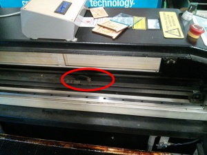
| + | #[[File:Laser-y-axis-plug-location.jpg|frameless|border|Location of the plug in the laser]] | ||
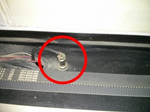
| + | #[[File:Laser-y-axis-plug-location-closeup.jpg|frameless|border|What the plug looks like]] | ||
| + | # Connect the Rotary tool to the vacant Y-Axis socket, and align the rotary tool parallel to the Y-axis carriage. | ||
| + | # Power up the laser-cutter and lower the Z-axis so that the rotary tool chuck is clear of the laser cutting head, roughly 10 inches down. | ||
| + | # Mount your workpiece in the Rotary Tool Chuck, and check it is straight by rotating the Y-Axis. | ||
| + | # Make sure the area you intend to engrave is at least 2 inches from the chuck of the rotary tool as the head needs space to accelerate either side of the work area. If the work area is right up against the chuck, then the laser head WILL HIT THE CHUCK as the head needs space to run up to speed either side of the work area. This can be deceptive as the "test" function which shows the work area outline does not include run-up distance either side. | ||
| + | # Position the rotary tool and workpiece underneath the laser head. '''Make sure the head is entirely clear of the rotary tool'''. | ||
| + | # Turn the laser back on. Move the head left and right and using the aiming dot to put the laser above the centre of the workpiece. '''Be very careful using the X-axis movement control as the speed travel will suddenly make the laser head slam into either the chuck or the centring cone. We recommend disabling speed travel during the software laser config by setting the quick speed to the same as start speed on the X-axis in the machine options screen.''' | ||
| + | # At the end of these steps, you should have a setup that looks like this: | ||
| + | |||
| + | [[File:Rotary-tool-complete-setup.jpg|frameless|border|The complete rotary tool setup]] | ||
| + | |||
| + | ==== Chuck ==== | ||
| + | |||
| + | There are two sets of chuck bits (grips), one set with inward facing grips the other with outward facing grips. When changing/adjusting the chuck note that these parts are numbered (1,2 & 3) as are the slots they go into (stamped inside the slot). Match part numbers to slots and once inserted close the chuck to ensure that the grips are even and centered. It can take a lot of faff and re-inserting to get the grips centered. | ||
| + | |||
| + | === Software Setup === | ||
| + | |||
| + | [[File:Machine-options-y-axis-pulse-unit.png|thumbnail|LaserCut Machine Options - Pulse unit]] | ||
| + | |||
| + | In laser-cut, you need to adjust the settings for your workpiece to reflect the circumference of your workpiece. | ||
| + | # Measure the circumference of your workpiece, as accurately as you can (diameter times Pi). | ||
| + | # Open LaserCut, click File...Machine-Options and select "Worktable" from the left-hand side. | ||
| + | # You need to change the "Pulse Unit" value under "Y Axis". The normal value of this setting is '''0.0048'''. | ||
| + | # To calculate the value, click the "..." button to the right of the text box. | ||
| + | # Enter the circumference of your workpiece in millimetres into the "Move" text box. | ||
| + | # Enter '''10000''' into the "Need pulse" text box. Click OK. | ||
| + | # Click "Save", then "OK", then "Close." A password is asked for. The password field has a prefilled value. Just accept it. | ||
| + | |||
| + | === Job Setup === | ||
| + | |||
| + | # Import and setup your job as normal. | ||
| + | # When you download your job, click ''Download CFG'' first. This will update the laser settings. | ||
| + | |||
| + | |||
| + | === Target Setup === | ||
| + | |||
| + | When the laser is powered on it will go through a datum to reset the laser position. With the y--axis disconnected this causes the laser to move to the far right and the rotary tool to rotate endlessly. You need to press stop to stop this. The datum rotation and stop are fast and abrupt for fragile targets (like glass). Experience says start the laser, complete the datum ''then'' mount the target. The rotation speed during lasering, when setup as above, much gentler and the grip on a fragile target does not need to be over tight. | ||
| + | |||
| + | When setting the Z-axis (and focus) be aware that in action the laser head overshoots the design X-width by quite a bit. Please ensure the laser head is higher than the chuck and the entire target. | ||
| + | |||
| + | == Running your job == | ||
| + | |||
| + | # Move the rotary tool so that the laser head is at the right-hand edge of your job (just like you would using the laser normally) | ||
| + | # With the Z-Axis still dropped so that the laser cutting head is above the rotary tool chuck, test the cut area with the laser cutter lid open. Ensure you are ready with the emergency stop in case the head is about to crash. | ||
| + | # If the laser head does not run the risk of approaching the Rotary Tool chuck, raise the Z-axis so that the laser is focused on the piece as usual. | ||
| + | # ''Carefully'' adjust the position of the rotary tool so the top of the workpiece is aligned with the laser head all the way along the x-axis. If using the lines of the honeycomb to check square, you might want to check the honeycomb is square in the bed first as it can slide about easily. | ||
| + | # Again, test the cut with the lid open and your hand ready on the emergency stop. Sometimes changing the laser config can have unexpected effects. | ||
| + | # Be aware that the laser head does not move at full speed when running the test to draw the cut outline. For example, on an "engrave" operation, when you run the test, the head will calmly trace the outline of the area to be engraved, but on the actual cut operation the head will overshoot the cut area by at least 1 inch as it has to accelerate up to speed before passing over the cut area. You must have a few inches of clearance between the cut area and the rotary chuck head in the X-axis, else you risk the laser head hitting the rotary chuck during the cut, even if the test looks fine. Simply put, do not have your cut area right up against the jaws of the chuck, such as with small parts. You will need to make a holder or extension to mount the small part further from the chuck (see video). | ||
| + | # {{#widget:YouTube|id=zuu8xkhYpYA|width=640}} | ||
| + | # If it all looks good, go ahead and close the lid and start the cut. | ||
| + | |||
| + | == Finishing up == | ||
| + | |||
| + | # Use the ''Reset LaserCut'' shortcut on the desktop to ensure the settings are back to normal for the next user. | ||
| + | # Use ''Download CFG'' to reset the laser itself | ||
| + | # Switch the laser off, unplug and remove the rotary tool. | ||
| + | # Plug the Y-axis back in. | ||
| + | # Start the laser, datum and cut a test job to ensure the settings are back to normal. | ||
| + | |||
| + | ==Example Projects== | ||
| + | |||
| + | {{#widget:YouTube|id=3xTextdiqHA|width=640}} | ||
| + | |||
| + | {{#widget:YouTube|id=zg0thiHPByg|width=640}} | ||
Latest revision as of 08:04, 9 May 2023
| Rotary Tool | |
|---|---|
 | |
| Manufacturer | Generic chinese |
| Model | Chuck Type |
| Obtained | Pledge Drive (July 2014) |
| Location | Laser Area |
| Team | Laser |
| Induction Required | No |
| Tools: all pages • list • Power Tools • Broken tools {{}} | |
| Warning: Incorrect usage of this tool can seriously damage the laser and its control electronics! |
The rotary tool allows cylindrical objects to be etched on the laser such as acrylic rods, glassware, anodised aluminium round parts, etc.
Setup
The rotary tool effective replaces the Y-Axis of the machine.
| Warning: Never disconnect the Y-Axis motor or the rotary tool whilst the laser cutter is powered on, this will damage the control electronics in the machine. |
Machine Setup
- Turn on and datum the laser as normal.
- Move the y-axis to about 1/3 away from the front of the cutter - after this step you won't be able to move the head forward/backward, so this just puts it in a sensible position.
- Make sure you can still access the metal cable connector on the right hand side (see pictures) as it can be obscured by the Y-axis.
- Turn the laser off (Remove card, press sign out and wait for the laser to shutdown)
- Disconnect the Y-Axis motor located to the right of the laser bed (see pictures). You need to unscrew the locking collar before removing it, and the pins can be quite stiff. Note the connector is keyed, will only fit in one way round. The socket itself is loose enough to twist so check the plug/socket keys are lined up when inserting the plug.
- Connect the Rotary tool to the vacant Y-Axis socket, and align the rotary tool parallel to the Y-axis carriage.
- Power up the laser-cutter and lower the Z-axis so that the rotary tool chuck is clear of the laser cutting head, roughly 10 inches down.
- Mount your workpiece in the Rotary Tool Chuck, and check it is straight by rotating the Y-Axis.
- Make sure the area you intend to engrave is at least 2 inches from the chuck of the rotary tool as the head needs space to accelerate either side of the work area. If the work area is right up against the chuck, then the laser head WILL HIT THE CHUCK as the head needs space to run up to speed either side of the work area. This can be deceptive as the "test" function which shows the work area outline does not include run-up distance either side.
- Position the rotary tool and workpiece underneath the laser head. Make sure the head is entirely clear of the rotary tool.
- Turn the laser back on. Move the head left and right and using the aiming dot to put the laser above the centre of the workpiece. Be very careful using the X-axis movement control as the speed travel will suddenly make the laser head slam into either the chuck or the centring cone. We recommend disabling speed travel during the software laser config by setting the quick speed to the same as start speed on the X-axis in the machine options screen.
- At the end of these steps, you should have a setup that looks like this:


Chuck
There are two sets of chuck bits (grips), one set with inward facing grips the other with outward facing grips. When changing/adjusting the chuck note that these parts are numbered (1,2 & 3) as are the slots they go into (stamped inside the slot). Match part numbers to slots and once inserted close the chuck to ensure that the grips are even and centered. It can take a lot of faff and re-inserting to get the grips centered.
Software Setup

In laser-cut, you need to adjust the settings for your workpiece to reflect the circumference of your workpiece.
- Measure the circumference of your workpiece, as accurately as you can (diameter times Pi).
- Open LaserCut, click File...Machine-Options and select "Worktable" from the left-hand side.
- You need to change the "Pulse Unit" value under "Y Axis". The normal value of this setting is 0.0048.
- To calculate the value, click the "..." button to the right of the text box.
- Enter the circumference of your workpiece in millimetres into the "Move" text box.
- Enter 10000 into the "Need pulse" text box. Click OK.
- Click "Save", then "OK", then "Close." A password is asked for. The password field has a prefilled value. Just accept it.
Job Setup
- Import and setup your job as normal.
- When you download your job, click Download CFG first. This will update the laser settings.
Target Setup
When the laser is powered on it will go through a datum to reset the laser position. With the y--axis disconnected this causes the laser to move to the far right and the rotary tool to rotate endlessly. You need to press stop to stop this. The datum rotation and stop are fast and abrupt for fragile targets (like glass). Experience says start the laser, complete the datum then mount the target. The rotation speed during lasering, when setup as above, much gentler and the grip on a fragile target does not need to be over tight.
When setting the Z-axis (and focus) be aware that in action the laser head overshoots the design X-width by quite a bit. Please ensure the laser head is higher than the chuck and the entire target.
Running your job
- Move the rotary tool so that the laser head is at the right-hand edge of your job (just like you would using the laser normally)
- With the Z-Axis still dropped so that the laser cutting head is above the rotary tool chuck, test the cut area with the laser cutter lid open. Ensure you are ready with the emergency stop in case the head is about to crash.
- If the laser head does not run the risk of approaching the Rotary Tool chuck, raise the Z-axis so that the laser is focused on the piece as usual.
- Carefully adjust the position of the rotary tool so the top of the workpiece is aligned with the laser head all the way along the x-axis. If using the lines of the honeycomb to check square, you might want to check the honeycomb is square in the bed first as it can slide about easily.
- Again, test the cut with the lid open and your hand ready on the emergency stop. Sometimes changing the laser config can have unexpected effects.
- Be aware that the laser head does not move at full speed when running the test to draw the cut outline. For example, on an "engrave" operation, when you run the test, the head will calmly trace the outline of the area to be engraved, but on the actual cut operation the head will overshoot the cut area by at least 1 inch as it has to accelerate up to speed before passing over the cut area. You must have a few inches of clearance between the cut area and the rotary chuck head in the X-axis, else you risk the laser head hitting the rotary chuck during the cut, even if the test looks fine. Simply put, do not have your cut area right up against the jaws of the chuck, such as with small parts. You will need to make a holder or extension to mount the small part further from the chuck (see video).
- If it all looks good, go ahead and close the lid and start the cut.
Finishing up
- Use the Reset LaserCut shortcut on the desktop to ensure the settings are back to normal for the next user.
- Use Download CFG to reset the laser itself
- Switch the laser off, unplug and remove the rotary tool.
- Plug the Y-axis back in.
- Start the laser, datum and cut a test job to ensure the settings are back to normal.
Example Projects