Difference between revisions of "Les Plywood"
m |
m (revert to in progress project) |
||
| Line 1: | Line 1: | ||
| − | {{Project|image=File:Les Plywood - Test fitting neck pocket.jpg|ProjectTitle=Les Plywood|created=21/12/2018|members=[[User:danspencer101|danspencer101]]|qrmode=0|status= | + | {{Project|image=File:Les Plywood - Test fitting neck pocket.jpg|ProjectTitle=Les Plywood|created=21/12/2018|members=[[User:danspencer101|danspencer101]]|qrmode=0|status=In Progress}} |
Can a Les Paul guitar be produced through laser cutting? Probably, yes but anyone who knows anything about guitars would ask why... | Can a Les Paul guitar be produced through laser cutting? Probably, yes but anyone who knows anything about guitars would ask why... | ||
Well, I wanted to give this a go for no real reason other than its something to do that will challenge my skills. | Well, I wanted to give this a go for no real reason other than its something to do that will challenge my skills. | ||
Revision as of 23:38, 5 January 2019
| Les Plywood | |
|---|---|
 | |
| Created | 21/12/2018 |
| Members | danspencer101 |
| Status | In Progress |
Can a Les Paul guitar be produced through laser cutting? Probably, yes but anyone who knows anything about guitars would ask why... Well, I wanted to give this a go for no real reason other than its something to do that will challenge my skills. I am under no illusions that plywood is not an ideal material for an electric guitar but I'm going to try it anyway!
Making the Body
CAD
Model in Fusion 360
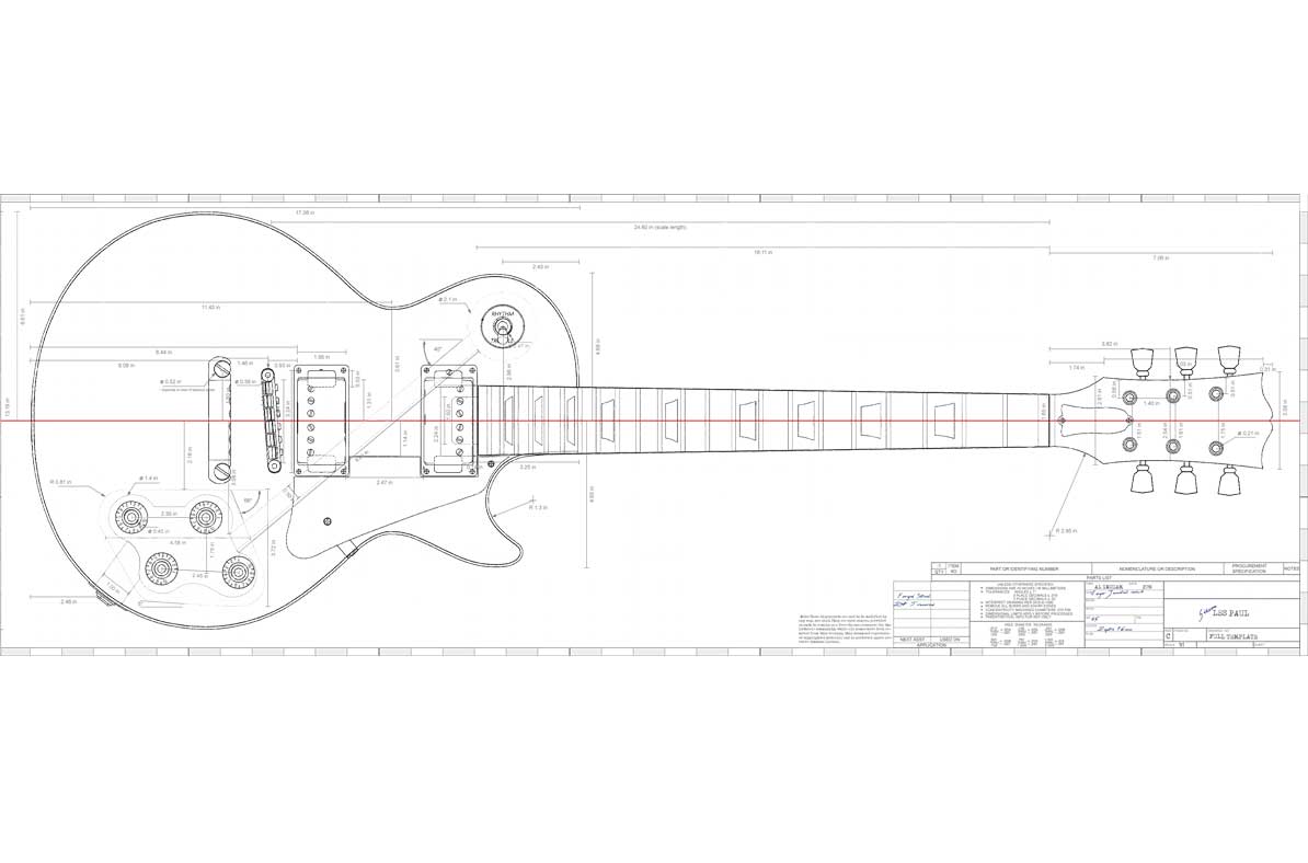
First things first I needed a model to create the DXF files for the laser cutter. I used a reference image that I found online and modelled it up in Fusion 360. See Here for the reference I used. I have deviated slightly from the plan as it is very badly drawn and doesn't follow any engineering standards at all. Anyway, it was good enough for me to put together a model :)

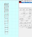
Once I had the model in Fusion 360 I produced a stack of planes that intersected the model and put a blank sketch on each of these planes. I then named all of the sketches to DXF Sketch 1 through to 8 as shown in the image. To pick up the geometry of the model you need to do an intersect in the sketch, its not automatic as I first thought. Then right click the sketch and save to DXF.


Arrange in Inkscape
With the DXF stack ready I then moved over to inkscape. Importing the sketches one at a time (Making sure to check that I was working in mm) and arranging them onto the 800mmx600mm page resulted in something that looks like this. These can then be taken over to Lasercut5.3 via any method you prefer.

Laser Cutting
I took a couple of videos and have uploaded them to youtube. See below.
Apologies about the vertical video, what was I thinking!
Gluing
Alignment
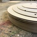
I put some through going 5mm holes into the model for aligning the stack. I used M5 machine bolts and was able to unscrew them once the glue dried. This alignment method has worked quite well but hasn't resulted in a perfectly smooth external surface. Oh well, the imperfections can be sanded away and any that remain will just add character. The very top layers were aligned using 10mm dowels in the holes where the bridge will go. Seemed to work ok!


Clamping Arrangement
Stage 1
Stage 2

.jpeg)
Result
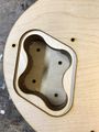
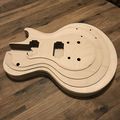
Electronics Pocket
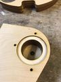
Pickup Selector Pocket
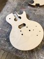
Flat Top (Note this picture was taken before I glued on the curve top layers)
With the curve top on
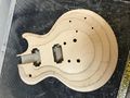
Another with the curve top on


Sanding
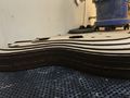
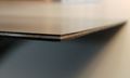
I hadn't originally intended to sand this at all but the edges were just a bit too rough due to the misalignment between layers and it didn't feel nice to hold so my hand was forced. The top was sanded using the mouse/ palm sander in the dusty area. I wanted to maintain the layered look of the laser cut layers so didn't go over the top; just broke the sharp edges.
For the edges I used a combination of the disk sander and a drill mounted drum sander, both inside the dusty area. This worked well and has made the guitar nicer to hold whilst maintaining the characteristic layered effect of the ply.
Layers easily visible on the Edge but overall quite smooth
Top View
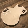
Back View
Curve Top


Building the neck


CAD
I have modelled the neck with a 5 degree angle from the body and a 15 degree head stock angle. The truss rod slot was modelled in to suit the one I ordered. I'd like to do the majority on the laser with ply and then glue an approx 5mm thick hardwood veneer on top for the fret board.
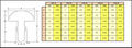
Fret Positions
The model I'm producing has a scale length of 625mm. That is the distance of the vibrating length of string, as the scale length affects the sound the guitar makes it is important to get the frets in position as accurately as possible. The numbers below were taken from the fret calculator here: https://www.stewmac.com/FretCalculator
| Fret | Distance from nut | Fret to Fret Distance |
|---|---|---|
| 1 | 35.079mm | 35.079mm (nut-1) |
| 2 | 68.188mm | 33.110mm (1-2) |
| 3 | 99.440mm | 31.251mm (2-3) |
| 4 | 128.937mm | 29.497mm (3-4) |
| 5 | 156.779mm | 27.842mm (4-5) |
| 6 | 183.058mm | 26.279mm (5-6) |
| 7 | 207.863mm | 24.804mm (6-7) |
| 8 | 231.275mm | 23.412mm (7-8) |
| 9 | 253.373mm | 22.098mm (8-9) |
| 10 | 274.231mm | 20.858mm (9-10) |
| 11 | 293.918mm | 19.687mm (10-11) |
| 12 | 312.500mm | 18.582mm (11-12) |
| 13 | 330.039mm | 17.539mm (12-13) |
| 14 | 346.594mm | 16.555mm (13-14) |
| 15 | 362.220mm | 15.626mm (14-15) |
| 16 | 376.969mm | 14.749mm (15-16) |
| 17 | 390.890mm | 13.921mm (16-17) |
| 18 | 404.029mm | 13.140mm (17-18) |
| 19 | 416.431mm | 12.402mm (18-19) |
| 20 | 428.137mm | 11.706mm (19-20) |
| 21 | 439.186mm | 11.049mm (20-21) |
| 22 | 449.615mm | 10.429mm (21-22) |
Gathering Materials
DHP-20 Wire
Fret Board, Fret wire and Truss Rod
Truss Rod Thickness


Fret Board
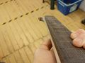
I was keen to have a dark wood for the fret board so ordered a piece of Indian Rosewood from Ebay; Thickness is approximately 7mm. The price including postage was £12.30. The piece was a little bit larger than I required so I tested a few different cutting parameters in the laser cutter to determine the best values for cutting the fret locations and cutting through the total thickness.
https://www.ebay.co.uk/itm/Guitar-Indian-Rosewood-Fretboard-luthier-Tonewood/123489924277
Fret Wire
I ordered 1.8m of DHP-20 fret wire from eBay. Not sure if this means anything to anyone, it doesn't to me! Total cost including postage was almost £20, quite pricey for the length of wire but seems to be about the going rate.
Truss Rod
In order to adjust the action of the neck, a truss rod is needed. Without looking into it too much I ordered this 480mm dual action one from ebay at a cost of just under £10: https://www.ebay.co.uk/itm/391966334841
It has now arrived and is exactly the width of two sheets of 3mm plywood! This makes me very happy as it massively simplifies the neck construction.
Laser Cutting

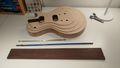
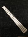
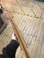
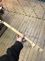
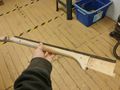
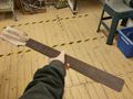
Laser cutting the neck parts proved easier than I expected and the project appears to actually look like a guitar now!
I was able to contruct planes and extract the sketches from fusion no problems this time round using the same method as for the body. The added benefit of the neck being that this part of the guitar is symmetrical so I only needed to export one side. Result. I also exported a sketch for the fret board; it is slightly more complicated than the rest in that I had to set up two sketches in Fusion 360 for one lasercut 5.3 program; one sketch for the outline and one for the fret locations. I overlayed the two sketches in Inkscape, worked great!
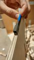
Laser cutting the neck itself went without a hitch really. There were some knots in the wood which meant the cut hadn’t quite gone through but Ian gave me a great tip of just finishing it off with a Stanley knife. Total material use was two sheets of 800x600mm and I probably could’ve reduced that further.
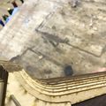
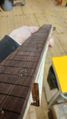
The fret board was slightly more nerve racking, for one the wood is much more expensive than ply so less room for error and two, I’m not very experienced with the laser at all yet and this would be the first time cutting something not on the helpful list at the Hackspace. The settings I eventually came to are shown in the gallery for this section. In addition to these settings I covered the part in masking tape to reduce scorching, worked very well. No fire so I consider that a massive success.
The depth of cut on the exterior profile was on the boarder line of ok; it didn’t cut cleanly through but with some mild persuasion the fret board did eventually come loose. For the fret wire cuts, it seems ok apart from the slight double cuts caused by my cad. Nothing superglue won’t fix I think.. I will come back to this when I actually get round to fitting the wire.
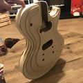
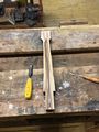
Neck heel
Testing the truss rod cavity
Lasercut Settings for 7mm thick Cherry
Masking to prevent scorch


Gluing the Neck
Feeling good about getting all the laser cutting done in one evening I thought I'd power through and go straight onto laminating the layers together. It started out really well; I cut some 3mm steel rod into short lengths to use as alignment pins and did a test fit. All seemed absolutely fine and I was happy to start gluing it together.
I stacked up the sections so that I could pick the top one off the pile, cover it in glue, slide it onto the alignment pegs and press together. This went really well for 3 or 4 layers but I quickly got out of sync with picking up the right layers and ended up having to remove layers I'd just glued, insert a new layer then return the one I'd just removed. Extremely frustrating! If I was to use this technique again I would add a number or identification mark onto each sketch in inkscape and engrave it during the laser cutting operation. That would've completely solved this problem.
The next issue was dropping the pot of wood glue I was using. In itself this isn't a problem, but, it meant that the nozzle broke and I lost the ability to apply the glue with precision. I switched putting a glob of glue onto the layer and spreading it with my finger, this meant that the amount of glue squeezing out when I pressed each layer down was ridiculous and very hard to manage. It became a really unwanted sticky white mess.
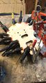
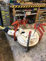
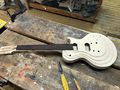
Clamping
When I brought the clamps out the 3mm plywood really started to show its weaknesses. Every time I applied pressure on the clamp the layers would bow, twist, pull apart at the top or bottom and generally do things I didn't want them to do. If I was to repeat this I would use a minimum of 6mm thick plywood as it would be a bit stiffer. I carried on regardless and used enough clamps to ensure that all the layers were well squeezed. Clamping arrangement will be shown in the gallery below.
Clamping arrangement on the headstock
Clamping arrangement on the neck


The result was generally quite good despite some bowing. Unfortunately I couldn't get in with a damp tissue to wipe all the squeezed out glue so it was quite messy prior to sanding.
Result
Straight after removing the clamps
Another shot


Preparing the Neck
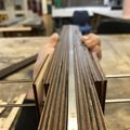
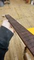
I used a combination of the mouse sander, the handheld belt sander and the disk sander in the dusty area to clean up and slightly smooth out the neck. I want to the guitar to be recognisably laser cut so I'm not going to be sanding the back of the neck into a perfectly round profile. You will be able to feel the lamination.
It was at this point I realised just how much the clamping has warped the component. Using the handheld belt sander I was able to flatten most of the bow across the neck caused by the clamping forces. Along the length, there is a definite wave going on; I believe its caused by how soft the layers of birch ply are causing them to deflect significantly when clamped together. I'm going to carry on regardless as the neck is slightly too wide for the fret board and the wave can be reduced through sanding or routing once the fret board is glued on. I'd recommend anyone doing this is the future to think about using profile clamps to try and reduce the warping effect.
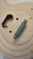
I checked after sanding that the truss rod still fit and was flush to the flat top. It was close, but didn't fit as the layers were slightly compressed. I had to use chisels to both widen and slightly deepen the pocket in a few areas (Mostly towards the heel of the neck). Whilst I had the chisels out I made sure that the tenon on the neck would fit snuggly into the pocket on the guitar body. I had to make a few adjustments to the pocket but it did eventually fit nice and tightly. I thought it important to do this before gluing on the fret board to reduce the risk of damaging the nice cherry wood with large chisels.
Truss rod fits in the slot
Test fitting the neck tennon & pocket

Gluing the fret board
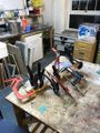
I started this operation by ensuring the truss rod was definitely in the slot; absolutely wouldn't want to have forgotten that. The fret board was covered with glue and then clamped up using a few quick clamps. No problems here as both faces were flat so there was no tendency for the fret board to twist. I left it to dry in the workshop for 24hrs on one of the benches with a Do Not Hack note.

Result
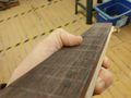
The result was a good bond between the fret board and neck; It is quite a bit meatier than I expected it to be, maybe I should've 3D printed a small section of the model just to check the grip. I'm not unhappy with the thickness, its feels very solid; it's just unexpected.
In the pictures you can see how much the neck sticks out from beyond the fret board. I think this has come from the plywood being a slightly different thickness from what I expected. Its worked out well though because I can sand this flush and take out the warping from the gluing operation.
Side view
The stick out can be seen here
Same situation on the other side
.jpeg)
.jpeg)
.jpeg)
Sanding the Neck
I sanded the sides of the neck flush with the fret board using the mouse sander, belt sander and just sand paper. I was a little bit too aggressive on the disc sander and have accidentally put a small notch on the fret board. I'm hoping it will sand out when I put the frets on.
Flush sides
Complete neck
Another shot of side
.jpeg)
.jpeg)
.jpeg)
Creating the Other Hardware
I could just buy this stuff in cheaply but I want to have a go at making it all my self. I'll try to document my thought & manufacturing processes as best as I can.
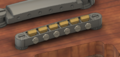
Tune-O-Matic Bridge

The tune-o-matic bridge is used to anchor the strings on the body of the guitar. There are two parts to it; the stop bar and the bridge itself.
CAD
The bridge assembly has been modelled below. There are no complicated over-hanging features meaning that it could be produced through conventional metal working processes or through casting. There are no notches for the strings on the bridge as these will be put in by hand. I haven't modelled the threads in for the pegs yet as I haven't researched what diameters I need to leave, I will fix these areas before cutting metal so I can tap threads.
Bridge

Anchors
Pegs
Bridge
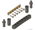
Exploded view of assembly


Stop Bar
Anchors
Pegs
Everything in place


3D Print Size Check
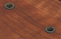
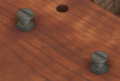
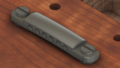
Although I was confident that the part would fit the guitar, I wanted to check that the radius on the top was OK as its quite hard to gauge through the computer screen. I was quite happy with the result! This was printed on my CR-10s at home but could easily have been done on the 3D Printer at the hackspace.
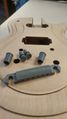
Parts before fitting
Fits nicely


String Spacing
In the initial revision, I modelled a string spacing of 8.75mm. Today I've checked the printed part against one of my guitars and it seems a little small so I will be increasing it to 10.4mm. This looks much more like the real part.


Manufacturing
Still unsure on how I will produce these parts. I think my options are:
- Simplify the model and manually Mill
- Some kind of CNC Milling
- Sand Casting
- Lost PLA Casting
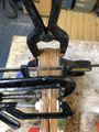
For the anchor and peg pieces, I have ordered some aluminium round bar and intend to produce these on either the CNC lathe or manual lathe.
Pickups
Intending to hand wind these.
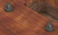
Strap Buttons
These will be cut on the Lathe using aluminium bar.
Pick Guard
I have ordered a sheet of 30cm x 30cm 3 Ply PVC sheet. As PVC is not laser safe I will be cutting this using the CNC Mill.
Although this material has already arrived it will be one of the last things I work on for this project.
Black, White, Black Laminations
