Difference between revisions of "Wall of Faces"
(→Boxes) |
m (Danspencer101 moved page Project:Wall of Faces to Wall of Faces over redirect) |
||
| (36 intermediate revisions by 8 users not shown) | |||
| Line 1: | Line 1: | ||
| − | = | + | {{project|created=01/04/2012|type=infrastructure|status=Dormant}} |
| − | |||
| − | |||
| − | |||
| − | The wall | + | == Overview == |
| − | + | The wall of faces will have members' photos and names on it. They will light up if a member is within the space.<br/> | |
| − | + | This was started as we grew and people could not put names to faces of members.<br/> | |
| − | + | This is an opt-in idea, people only make their unit if they would like to.<br/> | |
| − | + | Obviously a high-tech touch has been added.<br/> | |
| − | + | The wall will comprise of a number of boxes. Each box will have the members photo and name. <br/> | |
| + | The boxes will be laser cut and all fit together to build a whole wall. <br/> | ||
| + | Each box will also contain a circuit board. This will have LED backlighting and a microcontroller (probably an ATtiny48/85).<br/> | ||
| + | When a member is in the space (via their RFID tag) then their image will light up.<br/> | ||
| − | + | Members do not swipe out, so at the end of every day then all the backlighting will reset. This will give a record of who was in the space that day.<br/> | |
| + | An alternative of the above, of staying on till midnight, is that each box stay's lit for an amount of time (1 Hour?) after there last card swipe | ||
| + | This will probably be in the form of a kit which members get the chance to build - including laser cut pieces and soldering the board.<br/> | ||
| + | |||
| + | == Boxes == | ||
The boxes will be 60(h) x 60(l) x 30mm(w).<br> | The boxes will be 60(h) x 60(l) x 30mm(w).<br> | ||
The design was created using [http://boxmaker.rahulbotics.com/ BoxMaker].<br> | The design was created using [http://boxmaker.rahulbotics.com/ BoxMaker].<br> | ||
More on making project boxes is here http://support.ponoko.com/entries/20344437-laser-cut-project-box-tutorial.<br> | More on making project boxes is here http://support.ponoko.com/entries/20344437-laser-cut-project-box-tutorial.<br> | ||
| + | The initial prototype is here:<br> | ||
[[File:walloffaces1.jpeg|300px]] | [[File:walloffaces1.jpeg|300px]] | ||
[[File:walloffaces2.jpeg|300px]]<br><br> | [[File:walloffaces2.jpeg|300px]]<br><br> | ||
| Line 22: | Line 27: | ||
[[File:walloffaces4.jpeg|300px]]<br> | [[File:walloffaces4.jpeg|300px]]<br> | ||
| − | =Circuit= | + | == Circuit == |
| − | Use | + | * Use 4 RGB LED's [http://www.rapidonline.com/Electronic-Components/Piranha-Rgb-Led-72-8998] |
| − | Transistor to control LEDs | + | ** Phenoptix have these in either Common Anode or Cathode |
| − | ATtiny45/85 | + | ** http://www.phenoptix.com/index.php/through-hole/superflux-piranha/superflux-piranha-led-5mm-dome-rgb-ca.html |
| − | 4 way connector (male on 2 edges, female on 2 edges), so they can plug together as a grid. | + | ** http://www.phenoptix.com/index.php/through-hole/superflux-piranha/superflux-piranha-led-5mm-dome-rgb-cc.html |
| − | 4 wire: +5V , GND, CLOCK, DATA | + | ** Common anode by preference |
| + | * Transistor to control LEDs | ||
| + | ** NPN BC547 | ||
| + | * ATtiny45/85 | ||
| + | ** I've ordered up 5 ATTINY85V-10PU for testing --[[User:Lwk|'RepRap' Matt]] 18:18, 1 April 2012 (EST) | ||
| + | * 4 way connector (male on 2 edges, female on 2 edges), so they can plug together as a grid. | ||
| + | * 4 wire: +5V , GND, CLOCK, DATA | ||
| + | * I2C communications protocol | ||
| + | * ISP as test pads on under side, use pogo pins to connect via small holes in back panel | ||
| + | |||
| + | ===Pins Outs=== | ||
| + | ATtiny*5 | ||
| + | 1: N/C (ISP Reset) <br /> | ||
| + | 2: LED Red <br /> | ||
| + | 3: LED Green <br /> | ||
| + | 4: GND <br /> | ||
| + | 5: I2C SDA (ISP MOSI) <br /> | ||
| + | 6: LED BLU (ISP MISO) <br /> | ||
| + | 7: I2C SCL (ISP SCK) <br /> | ||
| + | 8: VCC <br /> | ||
| + | |||
| + | Useful info on programming ATtiny's with ArduinoISP<br /> | ||
| + | http://provideyourown.com/2011/arduino-program-attiny/ <br /> | ||
| + | Command to use <br /> | ||
| + | avrdude -P /dev/tty.usbserial-A600bN04 -b 19200 -c avrisp -p t85 -v -e -U flash:w:slave-attiny85.hex -U lfuse:w:0xe2:m -U hfuse:w:0xdf:m <br /> | ||
| + | Add 120ohm resistor between arduino rest and 5v<br/> | ||
| − | =Code= | + | == Code == |
Simple code - when a command comes through (a unique identifier) then the light swicthes ON (also can send an OFF command). | Simple code - when a command comes through (a unique identifier) then the light swicthes ON (also can send an OFF command). | ||
| − | =Main Controller= | + | Firmware available here<br/> |
| + | https://github.com/NottingHack/Wall-of-Faces | ||
| + | |||
| + | * http://code.google.com/p/arduino-tiny/ ATtiny core project, for using Arduino IDE | ||
| + | * http://code.google.com/p/arduino-tiny/wiki/TWIMasterLibrary I2c/TWI master Library for use with above, first glance might be out of date | ||
| + | * http://arduino.cc/playground/Code/USIi2c Playground article on the ATtiny I2C | ||
| + | |||
| + | Found this that might just work for us, maybe with a tweak to 10bit address<br /> | ||
| + | http://code.google.com/p/codalyze/wiki/CyzRgb | ||
| + | |||
| + | == I2C Command structure == | ||
| + | Need to define the command system for turning on and off the RGB led's<br /> | ||
| + | Needs to be simple so that changes down the line to add more functionality are only needed at the Main Controller rather than re-flashing every module<br/> | ||
| + | May follow BlinkM command structure http://thingm.com | ||
| + | |||
| + | Using the 10bit addressing with I2C<br/> | ||
| + | http://www.i2c-bus.org/addressing/10-bit-addressing/<br/> | ||
| + | Standard TWI/I2C on avr uses 7 bit address space this allows for 0-127 devices on a single bus, its possible to use a 10 bit address space but its going to need some custom code for both the ATmega328 and the ATtiny85 :( | ||
| + | |||
| + | I2C command table copied from CZY_RGB docs [http://code.google.com/p/codalyze/wiki/CyzRgb] and modified for 10bit address changes | ||
| + | {| class="wikitable" | ||
| + | | command name || cmd char || cmd byte || # args || # ret vals || format || implemented | ||
| + | |- | ||
| + | | Go to RGB Color Now || n || 0x6e || 3 || 0 || {‘n’,R,G,B} || yes | ||
| + | |- | ||
| + | | Fade to RGB Color || c || 0x63 || 3 || 0 || {‘c’,R,G,B} || yes | ||
| + | |- | ||
| + | | Fade to HSB Color || h || 0x68 || 3 || 0 || {‘h’,H,S,B} || yes | ||
| + | |- | ||
| + | | Fade to Random RGB Color || C || 0x43 || 3 || 0 || {‘C’,R,G,B} || yes | ||
| + | |- | ||
| + | | Fade to Random HSB Color || H || 0x48 || 3 || 0 || {‘H’,H,S,B} || yes | ||
| + | |- | ||
| + | | Play Light Script || p || 0x70 || 3 || 0 || {‘p’,n,r,p} || yes | ||
| + | |- | ||
| + | | Stop Script || o || 0x6f || 0 || 0 || {‘o’} || yes | ||
| + | |- | ||
| + | | Set Fade Speed || f || 0x66 || 1 || 0 || {‘f’,f} || yes | ||
| + | |- | ||
| + | | Set Time Adjust || t || 0x74 || 1 || 0 || {‘t’,t} || yes | ||
| + | |- | ||
| + | | Get Current RGB Color || g || 0x67 || 0 || 3 || {‘g’} || yes | ||
| + | |- | ||
| + | | Write Script Line || W || 0x57 || 7 || 0 || {‘W’,n,p,d,c,a1,a2,a3} || yes<sup>2</sup> | ||
| + | |- | ||
| + | | Read Script Line || R || 0x52 || 2 || 5 || {‘R’,n,p} || yes<sup>1</sup> | ||
| + | |- | ||
| + | | Set Script Length & Repeats || L || 0x4c || 3 || 0 || {‘L’,n,l,r} || yes | ||
| + | |- | ||
| + | | Set BlinkM Address || A || 0x41 || 6 || 0 || {‘A’,aH,aL,0xd0,0x0d,aH,aL} || yes | ||
| + | |- | ||
| + | | Get BlinkM Address || a || 0x61 || 0 || 2 || {‘a’} || yes | ||
| + | |- | ||
| + | | Get BlinkM Firmware Version || Z || 0x5a || 0 || 1 || {‘z’} || yes<sup>4</sup> | ||
| + | |- | ||
| + | | Set Startup Parameters || B || 0x42 || 5 || 0 || {‘B’,m,n,r,f,t} || yes | ||
| + | |- | ||
| + | | Pre-defined light scripts || colspan="6" | yes <sup>5</sup> | ||
| + | |} | ||
| + | <sup>x</sup> Only available in subversion head. <br/> | ||
| + | <sup>2</sup> Max 10 lines. Only valid commands are go and fade to RGB. Script number 'n' is ignored, can only write script 0 <br/> | ||
| + | <sup>4</sup> current head version returns 0.1 <br/> | ||
| + | <sup>5</sup> only script 1. no predenfined script 0. <br/> | ||
| + | |||
| + | *More on this to follow --[[User:Lwk|'RepRap' Matt]] 18:47, 1 April 2012 (EST) | ||
| + | |||
| + | == Main Controller == | ||
A controller will be required to take the info from gatekeeper (which knows when an RFID tag has been read) and output a command to turn on the correct box. | A controller will be required to take the info from gatekeeper (which knows when an RFID tag has been read) and output a command to turn on the correct box. | ||
| + | |||
| + | The Gatekeeper process on [[Holly]] will send ON commands with unique member id's <br/> | ||
| + | Posible a nanode with [https://github.com/njh/NanodeMQTT NanodeMQTT] to decode the MQTT and then send commands out via the I2C bus.<br/> | ||
| + | |||
| + | == Cost == | ||
| + | * ATtiny85 from RS ATTINY85V-10PU 696-2339P | ||
| + | ** 10+ £1.74 | ||
| + | ** 25+ £1.59 | ||
| + | * ATtiny45 from RS ATTINY45V-10PU 696-2320P | ||
| + | ** 10+ £1.38 | ||
| + | ** 25+ £1.26 | ||
| + | * RGB led's | ||
| + | * Headers | ||
| + | * PCB | ||
| + | * Capacitor | ||
| + | * Transistor | ||
| + | * Wood | ||
| + | ** 2 per box's per A4 sheet aprox | ||
| + | * Laser time | ||
| + | |||
| + | == Strong objections == | ||
| + | I have moved this to the [[{{TALKPAGENAME}}|Talk page]], as the page is for technical details of the project. [[User:James|James]] 09:09, 4 April 2012 (EST) | ||
| + | |||
| + | |||
[[Category:Projects]] | [[Category:Projects]] | ||
| − | |||
Latest revision as of 12:00, 5 February 2019
| Wall of Faces | |
|---|---|
| Created | 01/04/2012 |
| Status | Dormant |
| Type | Hackspace Infrastructure |
| QR code | |
Overview
The wall of faces will have members' photos and names on it. They will light up if a member is within the space.
This was started as we grew and people could not put names to faces of members.
This is an opt-in idea, people only make their unit if they would like to.
Obviously a high-tech touch has been added.
The wall will comprise of a number of boxes. Each box will have the members photo and name.
The boxes will be laser cut and all fit together to build a whole wall.
Each box will also contain a circuit board. This will have LED backlighting and a microcontroller (probably an ATtiny48/85).
When a member is in the space (via their RFID tag) then their image will light up.
Members do not swipe out, so at the end of every day then all the backlighting will reset. This will give a record of who was in the space that day.
An alternative of the above, of staying on till midnight, is that each box stay's lit for an amount of time (1 Hour?) after there last card swipe
This will probably be in the form of a kit which members get the chance to build - including laser cut pieces and soldering the board.
Boxes
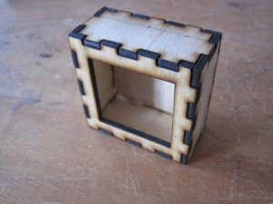
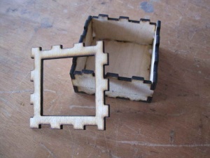
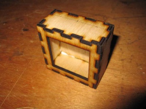
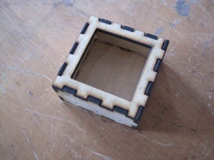
The boxes will be 60(h) x 60(l) x 30mm(w).
The design was created using BoxMaker.
More on making project boxes is here http://support.ponoko.com/entries/20344437-laser-cut-project-box-tutorial.
The initial prototype is here:


Circuit
- Use 4 RGB LED's [1]
- Phenoptix have these in either Common Anode or Cathode
- http://www.phenoptix.com/index.php/through-hole/superflux-piranha/superflux-piranha-led-5mm-dome-rgb-ca.html
- http://www.phenoptix.com/index.php/through-hole/superflux-piranha/superflux-piranha-led-5mm-dome-rgb-cc.html
- Common anode by preference
- Transistor to control LEDs
- NPN BC547
- ATtiny45/85
- I've ordered up 5 ATTINY85V-10PU for testing --'RepRap' Matt 18:18, 1 April 2012 (EST)
- 4 way connector (male on 2 edges, female on 2 edges), so they can plug together as a grid.
- 4 wire: +5V , GND, CLOCK, DATA
- I2C communications protocol
- ISP as test pads on under side, use pogo pins to connect via small holes in back panel
Pins Outs
ATtiny*5
1: N/C (ISP Reset)
2: LED Red
3: LED Green
4: GND
5: I2C SDA (ISP MOSI)
6: LED BLU (ISP MISO)
7: I2C SCL (ISP SCK)
8: VCC
Useful info on programming ATtiny's with ArduinoISP
http://provideyourown.com/2011/arduino-program-attiny/
Command to use
avrdude -P /dev/tty.usbserial-A600bN04 -b 19200 -c avrisp -p t85 -v -e -U flash:w:slave-attiny85.hex -U lfuse:w:0xe2:m -U hfuse:w:0xdf:m
Add 120ohm resistor between arduino rest and 5v
Code
Simple code - when a command comes through (a unique identifier) then the light swicthes ON (also can send an OFF command).
Firmware available here
https://github.com/NottingHack/Wall-of-Faces
- http://code.google.com/p/arduino-tiny/ ATtiny core project, for using Arduino IDE
- http://code.google.com/p/arduino-tiny/wiki/TWIMasterLibrary I2c/TWI master Library for use with above, first glance might be out of date
- http://arduino.cc/playground/Code/USIi2c Playground article on the ATtiny I2C
Found this that might just work for us, maybe with a tweak to 10bit address
http://code.google.com/p/codalyze/wiki/CyzRgb
I2C Command structure
Need to define the command system for turning on and off the RGB led's
Needs to be simple so that changes down the line to add more functionality are only needed at the Main Controller rather than re-flashing every module
May follow BlinkM command structure http://thingm.com
Using the 10bit addressing with I2C
http://www.i2c-bus.org/addressing/10-bit-addressing/
Standard TWI/I2C on avr uses 7 bit address space this allows for 0-127 devices on a single bus, its possible to use a 10 bit address space but its going to need some custom code for both the ATmega328 and the ATtiny85 :(
I2C command table copied from CZY_RGB docs [2] and modified for 10bit address changes
| command name | cmd char | cmd byte | # args | # ret vals | format | implemented |
| Go to RGB Color Now | n | 0x6e | 3 | 0 | {‘n’,R,G,B} | yes |
| Fade to RGB Color | c | 0x63 | 3 | 0 | {‘c’,R,G,B} | yes |
| Fade to HSB Color | h | 0x68 | 3 | 0 | {‘h’,H,S,B} | yes |
| Fade to Random RGB Color | C | 0x43 | 3 | 0 | {‘C’,R,G,B} | yes |
| Fade to Random HSB Color | H | 0x48 | 3 | 0 | {‘H’,H,S,B} | yes |
| Play Light Script | p | 0x70 | 3 | 0 | {‘p’,n,r,p} | yes |
| Stop Script | o | 0x6f | 0 | 0 | {‘o’} | yes |
| Set Fade Speed | f | 0x66 | 1 | 0 | {‘f’,f} | yes |
| Set Time Adjust | t | 0x74 | 1 | 0 | {‘t’,t} | yes |
| Get Current RGB Color | g | 0x67 | 0 | 3 | {‘g’} | yes |
| Write Script Line | W | 0x57 | 7 | 0 | {‘W’,n,p,d,c,a1,a2,a3} | yes2 |
| Read Script Line | R | 0x52 | 2 | 5 | {‘R’,n,p} | yes1 |
| Set Script Length & Repeats | L | 0x4c | 3 | 0 | {‘L’,n,l,r} | yes |
| Set BlinkM Address | A | 0x41 | 6 | 0 | {‘A’,aH,aL,0xd0,0x0d,aH,aL} | yes |
| Get BlinkM Address | a | 0x61 | 0 | 2 | {‘a’} | yes |
| Get BlinkM Firmware Version | Z | 0x5a | 0 | 1 | {‘z’} | yes4 |
| Set Startup Parameters | B | 0x42 | 5 | 0 | {‘B’,m,n,r,f,t} | yes |
| Pre-defined light scripts | yes 5 | |||||
x Only available in subversion head.
2 Max 10 lines. Only valid commands are go and fade to RGB. Script number 'n' is ignored, can only write script 0
4 current head version returns 0.1
5 only script 1. no predenfined script 0.
- More on this to follow --'RepRap' Matt 18:47, 1 April 2012 (EST)
Main Controller
A controller will be required to take the info from gatekeeper (which knows when an RFID tag has been read) and output a command to turn on the correct box.
The Gatekeeper process on Holly will send ON commands with unique member id's
Posible a nanode with NanodeMQTT to decode the MQTT and then send commands out via the I2C bus.
Cost
- ATtiny85 from RS ATTINY85V-10PU 696-2339P
- 10+ £1.74
- 25+ £1.59
- ATtiny45 from RS ATTINY45V-10PU 696-2320P
- 10+ £1.38
- 25+ £1.26
- RGB led's
- Headers
- PCB
- Capacitor
- Transistor
- Wood
- 2 per box's per A4 sheet aprox
- Laser time
Strong objections
I have moved this to the Talk page, as the page is for technical details of the project. James 09:09, 4 April 2012 (EST)