Laser cutter/Maintenance: Difference between revisions
Added break after pictures |
|||
| (10 intermediate revisions by the same user not shown) | |||
| Line 43: | Line 43: | ||
==== Cleaning the lens ==== | ==== Cleaning the lens ==== | ||
[[File:Air_Assist_Nozzle.jpg|320x240px|framed|right|Labelled picture of air assist nozzle]][[File:Lens_Collar.jpg|320x240px|framed|right|Labelled picture of lens collar]] | |||
You will need | [[File:Lens_Assembly.jpg|320x240px|framed|right|Labelled picture of lens assembly]] | ||
You will need isopropyl alcohol (IPA), a clean, dry lint-free cloth, the small metal tool, and a small table area to work at. | |||
# Ensure the laser is turned off. | |||
# While holding the air assist nozzle, unscrew the bottom grub screw as shown in the picture. This will free the air assist nozzle. Place it carefully on the bed. | |||
# While holding the lens assembly, unscrew the large collar as shown in the picture. Remove the lens assembly. | |||
# Sit down at your work area. This is important. You are less likely to drop the lens while sitting. | |||
# Using the small metal tool, unscrew the collar holding the lens in place. Carefully remove the lens and rubber washer. Keep the collar and washer safe. | |||
# Using the IPA and cloth, clean and dry the lens. Inspect it for burns or other marks/damage and record any possible issues to the laser@ email address. | |||
# Replace the lens and washer. The lens is fitted curved side down. Screw the collar back in. | |||
# You will probably have put fingerprints on the lens in step 7. Remove them with the IPA and cloth. | |||
# Fit the lens assembly back into the laser head and tighten the large collar. | |||
# Replace the air assist nozzle. | |||
# Turn the laser on. | |||
# Slowly move the head to the far right of the bed. Check that the air assist tubing and the alignment laser do not collide with the side of the laser. | |||
# Repeat step 12 at the far left. | |||
<br style="clear:both;" /> | |||
==== Cleaning the head mirror ==== | ==== Cleaning the head mirror ==== | ||
The head mirror must be removed to be cleaned. | The head mirror must be removed to be cleaned. | ||
You will need | You will need isopropyl alcohol (IPA), a clean, dry lint-free cloth, the large metal tool, and a small table area to work at. | ||
# Ensure the laser is turned off. | |||
# Using the large metal tool, unscrew the collar as shown in the picture. | |||
# Remove the mirror. | |||
# Sit down at your work area. This is important. You are less likely to drop the mirror while sitting. | |||
# Using the IPA and cloth, clean and dry the mirror. Inspect it for burns or other marks/damage and record any possible issues to the laser mailing list. | |||
# Replace the mirror and the collar. | |||
==== Cleaning the other mirrors ==== | ==== Cleaning the other mirrors ==== | ||
| Line 77: | Line 78: | ||
The back left mirror is accessed using a panel in the side of the laser. You cannot see it when cleaning it, so some assistance may be required. | The back left mirror is accessed using a panel in the side of the laser. You cannot see it when cleaning it, so some assistance may be required. | ||
# Ensure the laser is turned off. | |||
# Using the IPA and cloth, clean and dry the mirror. Inspect it for burns or other marks/damage and record any possible issues to the laser mailing list. | |||
=== Aligning the laser === | === Aligning the laser === | ||
| Line 86: | Line 87: | ||
You will need magnets, masking tape and the crosshair tool. | You will need magnets, masking tape and the crosshair tool. | ||
THIS PROCEDURE INTENTIONALLY DEFEATS THE 'OPEN LID' SAFETY CUTOUT. | The mirrors are adjusted using the gold adjuster knobs. The sprung bolts are tensioners which ensure the mirrors are pulled tight against the adjusters. | ||
EXERCISE EXTREME CAUTION WHILE CARRYING IT OUT. | |||
DO NOT ALLOW OTHERS ACCESS TO THE LASER ROOM. | [[File:MirrorAdjust.jpg|640x480px|framed|none|Stage mirror with labelled parts]] | ||
TO THE EXTENT POSSIBLE, DO NOT PLACE ANYTHING IN THE BEAM PATH. | |||
In order to alter the position of a mirror, turn the appropriate adjustment knob to push/pull the mirror in a particular direction. Note that this may move the mirror in more than one axis. | |||
'''THIS PROCEDURE INTENTIONALLY DEFEATS THE 'OPEN LID' SAFETY CUTOUT.''' | |||
'''EXERCISE EXTREME CAUTION WHILE CARRYING IT OUT.''' | |||
'''DO NOT ALLOW OTHERS ACCESS TO THE LASER ROOM.''' | |||
'''TO THE EXTENT POSSIBLE, DO NOT PLACE ANYTHING IN THE BEAM PATH.''' | |||
==== Aligning the horizontal beam ==== | ==== Aligning the horizontal beam ==== | ||
[[File:HeadMirrorAlignment.jpg|thumbnail|right|Head mirror with crosshair tool (and masking tape)]] | |||
# Close off access to the laser room using the orange strap. | |||
# Open the lid and place magnets on the safety cutout switch (see picture). | |||
# Turn the laser on. | |||
WARNING:THE LASER WILL NOW FIRE WITH THE LID OPEN. | '''WARNING:THE LASER WILL NOW FIRE WITH THE LID OPEN.''' | ||
# Place the crosshair tool in the laser head (see picture). | |||
# Place a piece of masking tape over the crosshair (see picture). | |||
# Briefly fire the laser. Note the position of the burn mark on the masking tape. | |||
# Adjust the front-left mirror as appropriate. | |||
# Repeat steps 6 and 7 until the mark is in the centre of the crosshair. Replace the tape when necessary. | |||
# Remove the magnets from the safety switch. | |||
==== Aligning the vertical beam ==== | ==== Aligning the vertical beam ==== | ||
| Line 108: | Line 119: | ||
This procedure uses a doubled-up piece of masking tape to avoid getting glue residue on the lens. | This procedure uses a doubled-up piece of masking tape to avoid getting glue residue on the lens. | ||
# Remove the air assist nozzle as described above in "Cleaning the Lens (Step 2)". | |||
# Take a 1" piece of masking tape and stick it back-to-back to a 3" piece of masking tape (so you have a 1" section that is not sticky). | |||
# Tape this onto the lens assembly as shown in the picture. | |||
# Briefly fire the laser. Note the position of the burn mark on the masking tape. | |||
# Adjust the head mirror as appropriate. | |||
# Repeat steps 4 and 5 until the mark is in the centre of the assembly. Replace the tape when necessary. | |||
# Replace the air assist assembly as described above in "Cleaning the Lens (Steps 10-13)". | |||
This completes alignment of the laser. | This completes alignment of the laser. | ||
Latest revision as of 01:17, 15 March 2015
This document describes the regular maintenance procedures required to keep the laser cutter in reliable service. It is intended as a guide for laser maintainers who have been trained in the procedures. Do not attempt to carry out the procedures yourself unless you have been trained.You may injure yourself and/or damage the laser cutter.
Parts
This document uses the following terms to refer to the various parts of the laser and the laser operation:
- x-axis - the axis of movement left/right when looking at the laser from the front.
- y-axis - the axis of movement forward/backward when looking at the laser from the front.
- z-axis - the axis of movement up/down.
- Laser head - the parts that direct the laser beam downwards onto the workpiece. It has a mirror, lens, red alignment laser and an air assist nozzle.
- Head mirror - the mirror in the laser head that reflects the beam from horizontal to vertical.
- Stage - the moving part that the laser head is attached to. Moves forwards/backwards to move the head in the Y-axis. Has parts to move head along it in the x-axis.
- Bed - the metal honeycomb and frame that workpieces rest on
Tools
The tools are kept in a box in the back-right of the laser. The panel is locked, so you will need a key. If you do not have one, email the laser mailing list.
- Large metal tool - used as screwdriver to remove mirror retention collars
- Small metal tool - used as screwdriver to remove lens retention collar
- Crosshair - used for aligning laser
Jobs
Levelling the Bed
Measuring
In general, but especially for large pieces of work, the bed must be level with respect to the stage. Actual level (that would be measured with a spirit level) doesn't matter as much as having a constant distance between the laser head and the workpiece.
Measure the distance in each of the corners:
- Move the head to the top-right of the bed.
- Measure the vertical distance from the top of the bed to the bottom of the stage. The exact point on the stage doesn't matter.
- Repeat steps 1 and 2 for the other three corners. Be sure to use the same point on the stage for each measurement.
Level the bed
TODO - LEVELLING INSTRUCTIONS
Cleaning the optics
The laser uses three mirrors and one lens to direct and focus the laser beam to the workpiece. These must be cleaned regularly to ensure good reflection/transmission of the beam.
These components are small,fragile and expensive. Be careful and cautious when removing, cleaning and installing.
Cleaning the lens
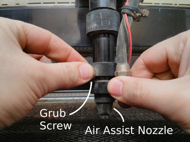
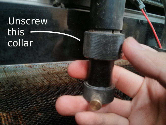
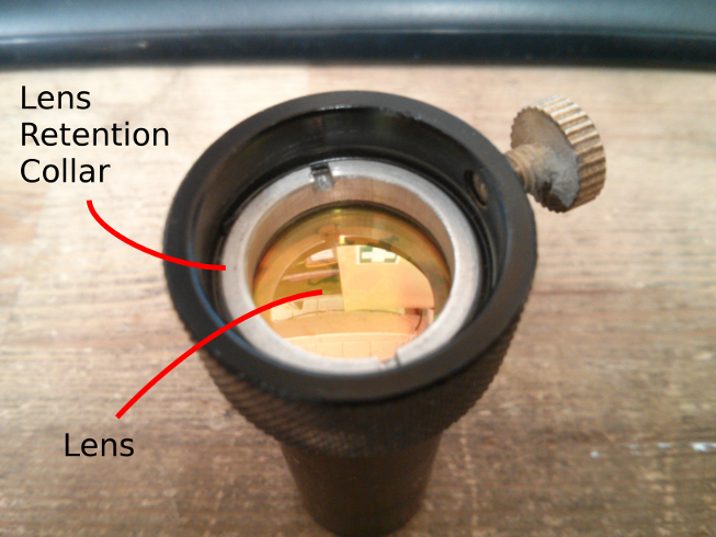
You will need isopropyl alcohol (IPA), a clean, dry lint-free cloth, the small metal tool, and a small table area to work at.
- Ensure the laser is turned off.
- While holding the air assist nozzle, unscrew the bottom grub screw as shown in the picture. This will free the air assist nozzle. Place it carefully on the bed.
- While holding the lens assembly, unscrew the large collar as shown in the picture. Remove the lens assembly.
- Sit down at your work area. This is important. You are less likely to drop the lens while sitting.
- Using the small metal tool, unscrew the collar holding the lens in place. Carefully remove the lens and rubber washer. Keep the collar and washer safe.
- Using the IPA and cloth, clean and dry the lens. Inspect it for burns or other marks/damage and record any possible issues to the laser@ email address.
- Replace the lens and washer. The lens is fitted curved side down. Screw the collar back in.
- You will probably have put fingerprints on the lens in step 7. Remove them with the IPA and cloth.
- Fit the lens assembly back into the laser head and tighten the large collar.
- Replace the air assist nozzle.
- Turn the laser on.
- Slowly move the head to the far right of the bed. Check that the air assist tubing and the alignment laser do not collide with the side of the laser.
- Repeat step 12 at the far left.
Cleaning the head mirror
The head mirror must be removed to be cleaned. You will need isopropyl alcohol (IPA), a clean, dry lint-free cloth, the large metal tool, and a small table area to work at.
- Ensure the laser is turned off.
- Using the large metal tool, unscrew the collar as shown in the picture.
- Remove the mirror.
- Sit down at your work area. This is important. You are less likely to drop the mirror while sitting.
- Using the IPA and cloth, clean and dry the mirror. Inspect it for burns or other marks/damage and record any possible issues to the laser mailing list.
- Replace the mirror and the collar.
Cleaning the other mirrors
These mirrors do not need to be removed to be cleaned. There is one mirror in the back left of the laser and one attached to the left of the stage.
The back left mirror is accessed using a panel in the side of the laser. You cannot see it when cleaning it, so some assistance may be required.
- Ensure the laser is turned off.
- Using the IPA and cloth, clean and dry the mirror. Inspect it for burns or other marks/damage and record any possible issues to the laser mailing list.
Aligning the laser
The laser beam ideally enters the laser head perfectly horizontally and in the centre of the hole. The head mirror then reflects it perfectly vertically into the centre of the lens. This procedure aims to acheive this within the tolerance expected from a manual procedure.
You will need magnets, masking tape and the crosshair tool.
The mirrors are adjusted using the gold adjuster knobs. The sprung bolts are tensioners which ensure the mirrors are pulled tight against the adjusters.
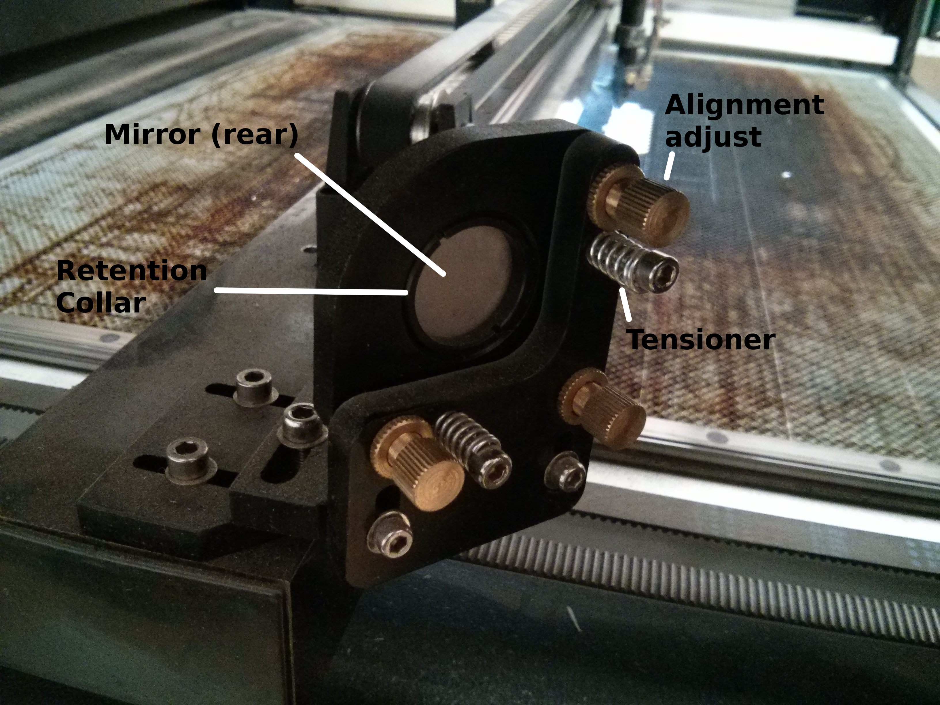
In order to alter the position of a mirror, turn the appropriate adjustment knob to push/pull the mirror in a particular direction. Note that this may move the mirror in more than one axis.
THIS PROCEDURE INTENTIONALLY DEFEATS THE 'OPEN LID' SAFETY CUTOUT.
EXERCISE EXTREME CAUTION WHILE CARRYING IT OUT.
DO NOT ALLOW OTHERS ACCESS TO THE LASER ROOM.
TO THE EXTENT POSSIBLE, DO NOT PLACE ANYTHING IN THE BEAM PATH.
Aligning the horizontal beam
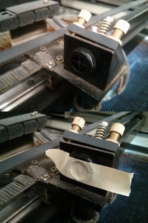
- Close off access to the laser room using the orange strap.
- Open the lid and place magnets on the safety cutout switch (see picture).
- Turn the laser on.
WARNING:THE LASER WILL NOW FIRE WITH THE LID OPEN.
- Place the crosshair tool in the laser head (see picture).
- Place a piece of masking tape over the crosshair (see picture).
- Briefly fire the laser. Note the position of the burn mark on the masking tape.
- Adjust the front-left mirror as appropriate.
- Repeat steps 6 and 7 until the mark is in the centre of the crosshair. Replace the tape when necessary.
- Remove the magnets from the safety switch.
Aligning the vertical beam
This procedure uses a doubled-up piece of masking tape to avoid getting glue residue on the lens.
- Remove the air assist nozzle as described above in "Cleaning the Lens (Step 2)".
- Take a 1" piece of masking tape and stick it back-to-back to a 3" piece of masking tape (so you have a 1" section that is not sticky).
- Tape this onto the lens assembly as shown in the picture.
- Briefly fire the laser. Note the position of the burn mark on the masking tape.
- Adjust the head mirror as appropriate.
- Repeat steps 4 and 5 until the mark is in the centre of the assembly. Replace the tape when necessary.
- Replace the air assist assembly as described above in "Cleaning the Lens (Steps 10-13)".
This completes alignment of the laser.
Finishing Up
Perform a test cut using an appropriate design and note the performance. As a guide, the minimum reasonable speed for cutting 3mm ply at 65% power is 20mm/s.
Notes
If you are having issues with carrying out the procedure, comments or questions, or want access to edit this document, please email the laser mailing list.