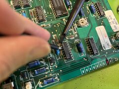
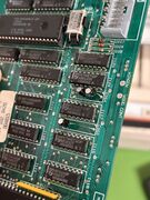
Philips VP406 LaserDisc Player Repair
| Philips VP406 Repair | |
|---|---|
 | |
| Primary Contact | Aaron / Tim |
| Created | 2025-03-26 |
| Members | Tim, JonW, Ali, Olivia, Aaron |
| Status | Active |
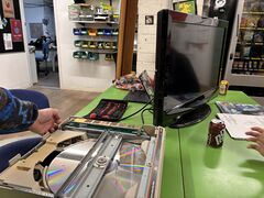
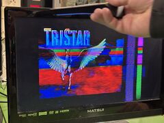
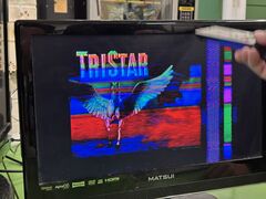
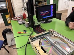
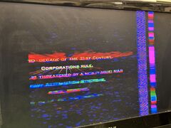
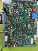
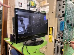
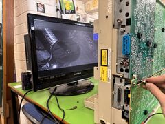
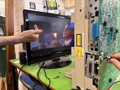
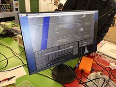
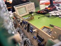
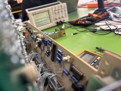
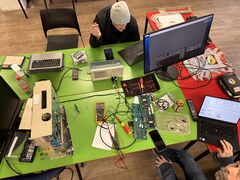
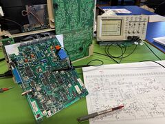
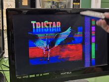
We're trying to fix a VP406 LaserDisc player. It lived under Tim's bed for many years and now we want to watch LaserDiscs during film night - but first, we must repair it. While the disc plays, and the TV syncs correctly, the video is offset. The issue appears to be before or around the PAL demodulator, since the on screen debugging menu is correctly positioned.
Resources
OCRd Service Manual for VP406 Player
Service manual for VP415 Player, pages 20-35 describe sending 'F-Codes' over RS232 to control things like 'jump to frame and freeze' which might be useful for getting a test pattern.
Schematics
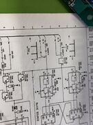
Ali has combined and cleaned up the scematics from the service manual. Much nicer! The wiki won't make thumbnails for them because they're chonky, but you can click through to the original file.
- Aa - TXT Bypass, PAL Demodulator, Luminance Delay, Colour Transient Improver, U/V Processing, RGB Matrix
- Ab - Slave Source, Focus, Focus Drive, Sandcastle Generator, Sync Insert, Vertical Blanking Insert
- B - Radial Drive, Time Base Correction (TBC), Audio CCD, Variable Delay Line, Delay Control, Video CCD
- Ca - HF Processing, Video Demodulation, Dropout Correction,
- Cb - Audio Processing, Slide Drive
- Da - Special Burst Separator, "Reference"
- Db - Sequencing
- F - Power Supply
- N-P - Front Panel Keys
- SRa - Control, Watchdog, RS232
- SRb - CPU, SBUS
- Z - Laser Supply, Servo Pre-Amplifier, Tilt Motor Control
Just the schematics are available in one PDF for easy browsing: File:VP406 AllSchematics.pdf (23MB).
Boards
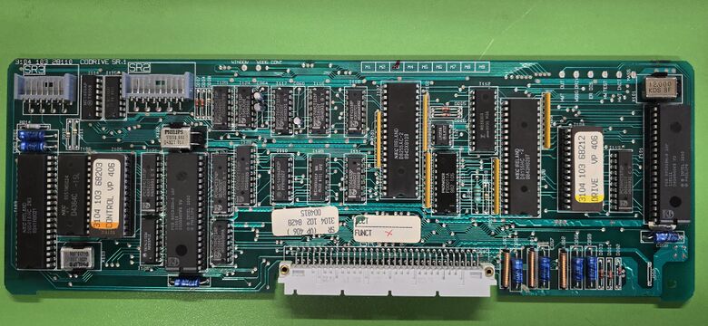
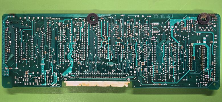
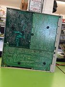
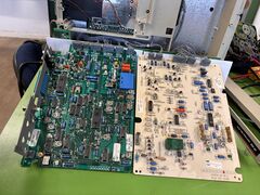
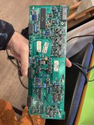
SR board
Contains SRa and SRb circuits combined into one board.
Timeline
26th March 2025
- Video plays, but is offset
- Power switch doesn't work - removed and bridged temporarily
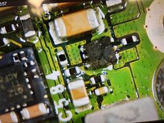
- X2 RIFA capacitor exploded - removed
29th March 2025
- Removed the other X2 capacitor, since it was probably also going to explode.
- Lots of debugging. We think the issue is not with Board A but Board D, which presumably creates a line pulse but out of phase from the video.
- Confirmed that the video feed going into the PAL modulator is alight, since the TV can sync to it.
What we want to check next:
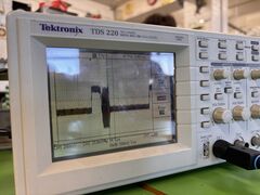
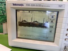
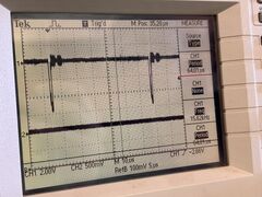
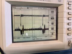
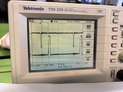
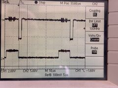
- Verify that HMANCH is being generated correctly by probing CVTBM and HMANCH at the same time (see page 44 of schematic). They should line up.
- Check that HMANCH isn't being inverted in some weird way by the "SLAVE SOURCE" (see page 34)
5th April 2025
- We verified that HMANCH is being generated correctly and in time with the disc's composite video.
- The logic in that area seems to be preferring the RAMP EN pulse instead of HMANCH. We suspect this may be causing the issue issue with the shifted frame.
- The laserdisc player died at some point while trying to figure out what the logic was doing.
- All power rails are good.
- Disconnecting the board we were working on does not help.
- A red LED lights on the front, nothing else happens.
Despite the issues with it turning on, I do want to document our current thoughts before we forget them trying to fix the other issue. Some context from page 129:
- The function of the slave source circuit is the generation of sync and timing signals for the video signal processing in the player. These reference signals have to be very accurate and are generated by a sync generator IC 7061 with a feedback oscillator (5MHz).
- During the start-up cycle of the player the sync generator will create the timing signals related to the free-running oscillator. The oscillator is readjusted dependent on the input signal of the sync generator, hence the name slave source. On behalf of the synchronism with the video signal of the disc a frame reset takes place, if necessary.
- Thus, at the end of the start-up cycle, a unique lock-in performance can be observed in the video picture. The slave source circuit can be split in two parts: the sync generator circuit, frame reset circuit.
- ... skip to Frame Reset Circuit
- If necessary, the frame reset circuit generates a frame reset pulse to lock sync generator IC 7061 to the video signal on the disc. Input signals VMANCH (vertical sync) and HMANCH (horizontal sync) have been derived from the video signal of the disc, CV-TBM (timebase corrected). The input signal of the sync generator, RAMP-EN, has been derived from the reference on module D and sees the to the drive of the turntable motor by means of the MCO signal after comparison with CV-DOC video signal coming from the disc. This CV-DOC signal has not yet been corrected for timebase and might drift relative to CV-TBM. To prevent this from happening the frame rest is required.
The sync pulses in the composite output of the player are aligned with RAMP-EN, rather than HMANCH, which comes slightly before it. The position of HMANCH would make much more sense, as it comes before the colour burst. The oscillator cannot be free running or the picture sync would move in and out of phase with the disc's video.
As for why the thing isn't doing anything now, we're still quite unsure. The red LED on the front suggests it's in standby, but pressing the standby or eject buttons should awaken it - this does not happen. The voltage rails all seem to be alive. A few ideas to check:
- Check to make sure the reset line on either CPU isn't stuck high, as this will cause the CPU to constantly reset.
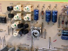
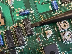
- 2060 and 2064 are electrolytics responsible for the output duration of the watchdogs' timer. We should check those, or just replace them. They are 4.7uF and 2.2uF respectively.
- Stick a logic analyser on 7107 - It's an IO expander on the codrive module. The serial lines should show the bit pattern flickering when buttons are pressed.
- Check A0 address line on the control processor, this should be toggling a lot if it's executing the code.
7th April 2025
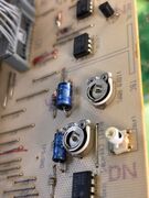
We've been investigating the watchdog for the drive processor and the control processor. The 2.2uF capacitor (2064) was discharging very quickly, so determined to be suspect. We decided to replace it with two 4.7uF capacitors in parallel, roughly giving 2.5uF. We also replaced the 4.7uF capacitor (2060) as a precaution. We then spent some time monitoring the signals involved in preventing the drive module's watchdog from triggering (via it's reset line).
We have determined that the drive processor's watchdog is being correctly reset via the output of shift register 7110, but still triggering after the data to the shift register stops. We suspect the processing is crashing, or waiting for information off the sbus. Will continue investigating...
21:32
The control processor is resetting its watchdog frequently, and the watchdog is not resetting the CPU. That's good. So, why is the drive processor crashing?
Ideas for next time
- Since the control processor appears to be running fine, we can probably talk to it over serial. Maybe we can get an error code.
- Get a logic trace of all the inputs to the drive processor, ensure we understand what they are doing, and use this to find out what might be wrong.
- Dump the drive program EPROM and disassemble it.
