Gatekeeper: Difference between revisions
No edit summary |
m Add pointer to card set up instructions, because I can never find it. |
||
| (One intermediate revision by one other user not shown) | |||
| Line 1: | Line 1: | ||
{{info|If you're after instructions to set up your RFID card, see [[HMS/Gatekeeper Setup]]}} | |||
'''Gatekeeper''' is the first node of our Hackspace Instrumentation project to go live and is responsible for access control to the space through the front "Airlock" door. An updated version is also used for the back entrance [[upstairs]] and several access doors [[downstairs]]. | '''Gatekeeper''' is the first node of our Hackspace Instrumentation project to go live and is responsible for access control to the space through the front "Airlock" door. An updated version is also used for the back entrance [[upstairs]] and several access doors [[downstairs]]. | ||
| Line 47: | Line 49: | ||
Some time the V1 hardware on the Airlock door needs resting by hand<br> | Some time the V1 hardware on the Airlock door needs resting by hand<br> | ||
The main board is located to the left of the Cash Acceptors in the Members storage area<br> | The main board is located to the left of the Cash Acceptors in the Members storage area<br> | ||
[[File: | [[File:Gatekeeper V1 Rear Context.jpg|400px]]<br> | ||
Cycle the power first by toggling the switch indicated by the purple arrow, then reset the Arduino (Red arrow) <br> | Cycle the power first by toggling the switch indicated by the purple arrow, then reset the Arduino (Red arrow) <br> | ||
Latest revision as of 14:14, 21 July 2024
| If you're after instructions to set up your RFID card, see HMS/Gatekeeper Setup |
Gatekeeper is the first node of our Hackspace Instrumentation project to go live and is responsible for access control to the space through the front "Airlock" door. An updated version is also used for the back entrance upstairs and several access doors downstairs.
Details
Pics
Source Code
The firmware that runs on the arduino can be found here
https://github.com/NottingHack/instrumentation-arduino
The code for the database and the process that run on Holly can be found here
https://github.com/NottingHack/instrumentation, the relevant part is GateKeeper.cpp
The PCB and housing designs can be found here
https://github.com/NottingHack/Gatekeeper-eagle
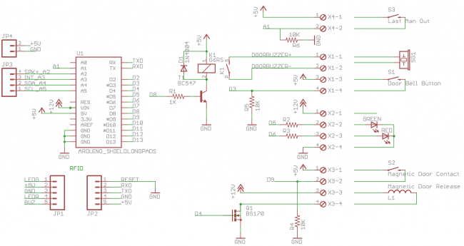
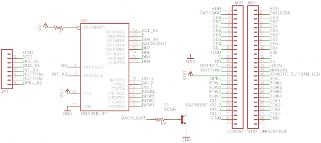
Schematic
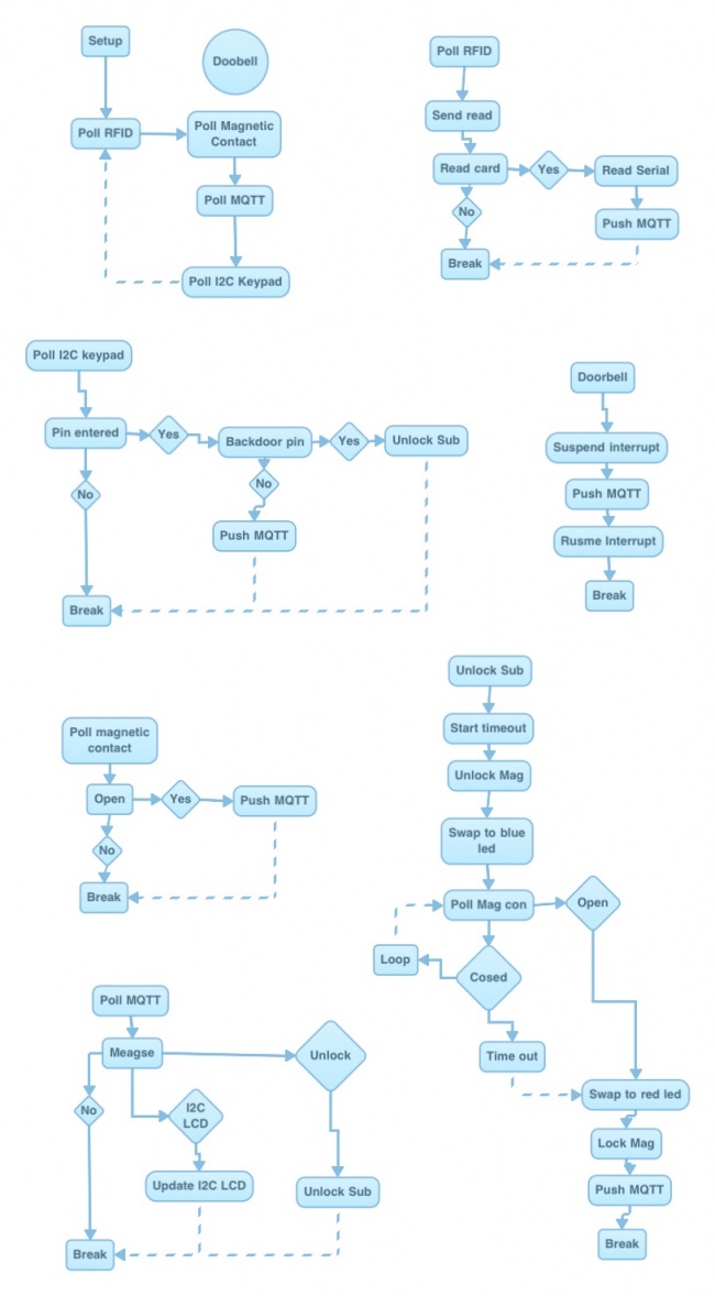
Logic Flow
Quick Breakdown
- Arduino with Wiznet shield
- RFID reader
- Doorbell button (interrupt pin)
- magnetic release (MOSFET switch 12v)
- Magnetic contact
- Doorbell sounder (Relay) - activated either by attached doorbell button, or doorbell on outer door (connected to main LED Matrix display)
- Magnetic release status led's red/blue (TODO)
- Matrix keypad and HD44780 LCD controlled via I2C AtTiny2313
- MQTT
- MQTT scripts on holly push door opened & last man switch events to irc twitter and log
- Card numbers in 'Instrumentation' MySQL database on Holly
- Database managed by HMS
Notes
6 Core alarm cable run to airlock door
- magnetic contact on black and white core
- door magnetic release green and yellow cores
- last man switch on blue and red cores
Reseting
V1
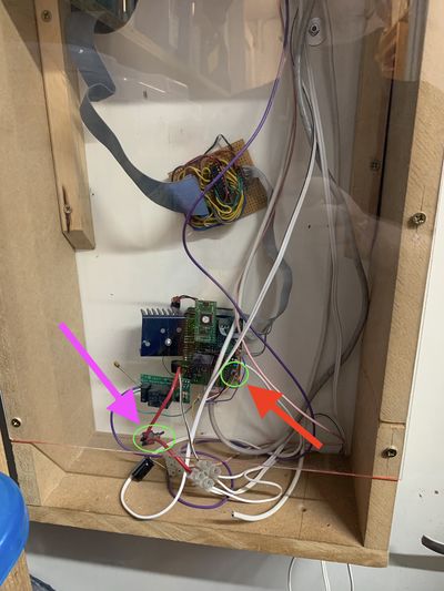
Some time the V1 hardware on the Airlock door needs resting by hand
The main board is located to the left of the Cash Acceptors in the Members storage area
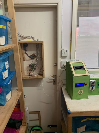
Cycle the power first by toggling the switch indicated by the purple arrow, then reset the Arduino (Red arrow)
V2
Open the grey box and hit the reset switch
