Lighting Automation/Control Box: Difference between revisions
No edit summary |
|||
| Line 9: | Line 9: | ||
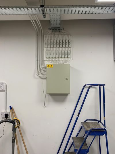
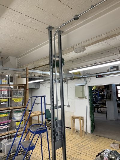
[[File:ClassRoomController Context.jpg|400px]] | [[File:ClassRoomController Context.jpg|400px]] | ||
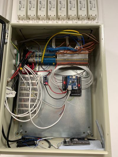
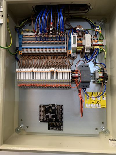
[[File:ClassRoomController Inside.jpg|400px]] | [[File:ClassRoomController Inside.jpg|400px]] | ||
===Workshop=== | |||
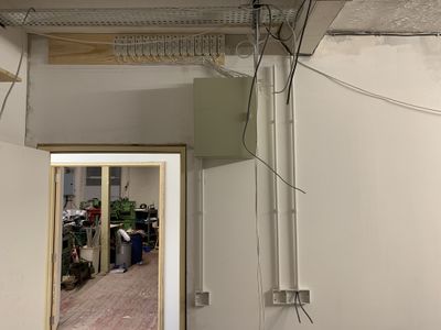
[[File:WorkshopController Context.jpg|400px]] | |||
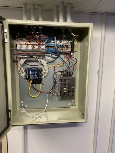
[[File:WorkshopController Inside.jpg|400px]] | |||
===Upstairs Members Storage=== | |||
[[File:StudioController Context.jpg|400px]] | |||
[[File:StudioController Inside.jpg|400px]] | |||
==Original Plans== | ==Original Plans== | ||
| Line 53: | Line 61: | ||
[[Category:Instrumentation]] | [[Category:Instrumentation]] | ||
[[Category:Lighting]] | |||
Latest revision as of 15:59, 30 October 2021
Details about the construction of the two controler box's
Current Control boxes
G4 CNC Room Box
G6 Classroom
Workshop
Upstairs Members Storage
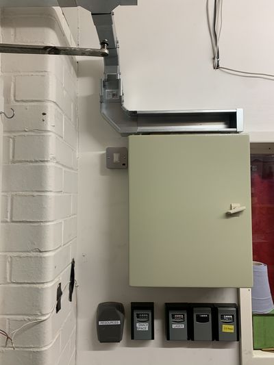 File:StudioController Inside.jpg
Original Plans
Gen 1 plans below
Contactors and Relay Holders
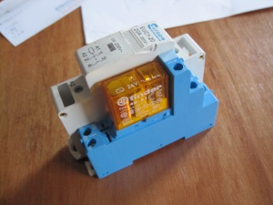
We have a mix of 2pole and 4 pole contators, most are rated for 20amp.
There is also a mix of SP and DB relay holders but we have 17 SP holders so should not need the DP holders
These are all din rail mounted so will make a nice clean install
Relays
We have some Finder 40.31 relays that arrived with the holders but they have 24vAC coils, these will be a pain to try and drive/switch form an arduino
Better suited to our needs are the following
Finder 40.31.7.012.0000
12vDC 10a SPDT miniature relay
Contacts are rated to 10amp 240v more that enough as we are just switching the contactor's
Coil specs
- 12vdc
- 300ohm
- 40mA @12v
We have Finder series 95 holders to mount these on the din rails
Power Supply
Michael Erskine has supplied use with one(hopefully to be two) 12v DC din rail mounted power supplies
Power one LOR4301-2, 12V 3.5A
These will be used to supply 12v switching power to the relays and power to the Xino
MCU
As always control will be provided by an Arduino, in this case a xino
For connection to the network a clone wiznet Shield will be use [1]
A custom shield fitted with two ULN2003a darlington arrays will be use to switch the relays, these arrays may in turn be switched by shift registers to save on pin usage
Arduino Shield
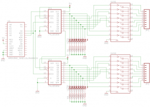
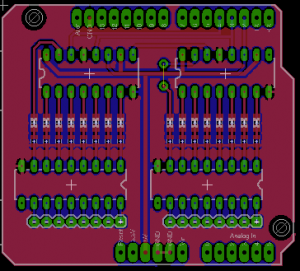
In order to save maximise on output shift registers (74HTC59N) were use to control the lights, this needs 3 pins form the arduino and can control 16 line with two registers. We are using Darlington Arrays (ULN2803A) to control the 12v relay coils, a high out put form the shift register allows current to flow through the darlington and hence charge the coil.
I've done a shield that will carry two shift registers and two darlington arrays, I also managed to get in some led's --'RepRap' Matt 08:48, 20 May 2012 (EST)
Updated shield to have surface mount LED's mad it easier to etch, first board has been produced already --'RepRap' Matt
