Philips VP406 LaserDisc Player Repair: Difference between revisions
Link about fcodes from vp415 doc |
|||
| (57 intermediate revisions by 3 users not shown) | |||
| Line 1: | Line 1: | ||
{{Project | {{Project | ||
|image= | |image=File:LaserDiscRepair 2025-03-26T193313 IMG 4876.jpg | ||
|name=Philips VP406 Repair | |name=Philips VP406 Repair | ||
|created=2025-03-26 | |created=2025-03-26 | ||
|primary=[[User:Asj|Aaron]] / [[User:Tim|Tim]] | |primary=[[User:Asj|Aaron]] / [[User:Tim|Tim]] | ||
|members=[[User:Tim|Tim]], [[User:Drjonwoodcock|JonW]], [[User:Ali1234|Ali]], [[User:Oliviaiacovou|Olivia]], [[User:Asj|Aaron]] | |members=[[User:Tim|Tim]], [[User:Drjonwoodcock|JonW]], [[User:Moop|Moop]], [[User:lwk|dpslwk]] [[User:Ali1234|Ali]], [[User:Oliviaiacovou|Olivia]], [[User:Asj|Aaron]] | ||
|status=Active | |||
|repo=https://github.com/mooped/vp406-laserdisc | |||
}} | }} | ||
We're trying to fix a VP406 LaserDisc player. It lived under Tim's bed for many years and now we want to watch LaserDiscs during film night - but first, we must repair it. While the disc plays, and the TV syncs correctly, the video is offset. The issue appears to be before or around the PAL demodulator, since the on screen debugging menu is correctly positioned. | We're trying to fix a VP406 LaserDisc player. It lived under Tim's bed for many years and now we want to watch LaserDiscs during film night - but first, we must repair it. While the disc plays, and the TV syncs correctly, the video is offset. The issue appears to be before or around the PAL demodulator, since the on screen debugging menu is correctly positioned. | ||
| Line 13: | Line 15: | ||
[https://www.domesday86.com/wp-content/uploads/2017/01/Philips-VP415-Operating-Instructions.pdf Service manual for VP415 Player], pages 20-35 describe sending 'F-Codes' over RS232 to control things like 'jump to frame and freeze' which might be useful for getting a test pattern. | [https://www.domesday86.com/wp-content/uploads/2017/01/Philips-VP415-Operating-Instructions.pdf Service manual for VP415 Player], pages 20-35 describe sending 'F-Codes' over RS232 to control things like 'jump to frame and freeze' which might be useful for getting a test pattern. | ||
== Schematics == | |||
Ali has combined and cleaned up the scematics from the service manual. Much nicer! The wiki won't make thumbnails for them because they're chonky, but you can click through to the original file. | |||
* [[:Image:LaserDiscRepair_Schematics_Aa.png|Aa]] - TXT Bypass, PAL Demodulator, Luminance Delay, Colour Transient Improver, U/V Processing, RGB Matrix | |||
* [[:Image:LaserDiscRepair_Schematics_Ab.png|Ab]] - Slave Source, Focus, Focus Drive, Sandcastle Generator, Sync Insert, Vertical Blanking Insert | |||
* [[:Image:LaserDiscRepair_Schematics_B.png|B]] - Radial Drive, Time Base Correction (TBC), Audio CCD, Variable Delay Line, Delay Control, Video CCD | |||
* [[:Image:LaserDiscRepair_Schematics_Ca.png|Ca]] - HF Processing, Video Demodulation, Dropout Correction, | |||
* [[:Image:LaserDiscRepair_Schematics_Cb.png|Cb]] - Audio Processing, Slide Drive | |||
* [[:Image:LaserDiscRepair_Schematics_Da.png|Da]] - Special Burst Separator, "Reference" | |||
* [[:Image:LaserDiscRepair_Schematics_Db.png|Db]] - Sequencing | |||
* [[:Image:LaserDiscRepair_Schematics_F.png|F]] - Power Supply | |||
* [[:Image:LaserDiscRepair_Schematics_N-P.png|N-P]] - Front Panel Keys | |||
* [[:Image:LaserDiscRepair_Schematics_SRa.png|SRa]] - Control, Watchdog, RS232 | |||
* [[:Image:LaserDiscRepair_Schematics_SRb.png|SRb]] - CPU, SBUS | |||
* [[:Image:LaserDiscRepair_Schematics_Z.png|Z]] - Laser Supply, Servo Pre-Amplifier, Tilt Motor Control | |||
Just the schematics are available in one PDF for easy browsing: [[:File:VP406 AllSchematics.pdf]] (23MB). | |||
== ROM Dumps == | |||
[[File:VP406 ROMs.zip]] | |||
= Boards = | |||
== A Board / "Video Proc Panel" == | |||
<gallery mode=packed-hover heights=240px> | |||
File:VP406_A_Board_Top.jpg | |||
File:VP406_A_Board_Bottom.jpg | |||
</gallery> | |||
== B Board / "Rad+TBC Panel" == | |||
Radial and Time Based Correction | |||
<gallery mode=packed-hover heights=240px> | |||
File:VP406_B_Board_Top.jpg | |||
File:VP406_B_Board_Bottom.jpg | |||
</gallery> | |||
== C Board / "HF+Audio Panel" == | |||
<gallery mode=packed-hover heights=240px> | |||
File:VP406_C_Board_Top.jpg | |||
File:VP406_C_Board_Bottom.jpg | |||
</gallery> | |||
== D Board / "Motorseq+TBC module" == | |||
<gallery mode=packed-hover heights=240px> | |||
File:VP406_D_Board_Top.jpg | |||
File:VP406_D_Board_Bottom.jpg | |||
</gallery> | |||
== N Board / "Keyboard module" == | |||
<gallery mode=packed-hover heights=240px> | |||
File:VP406_N_Board_Top.jpg | |||
File:VP406_N_Board_Bottom.jpg | |||
</gallery> | |||
== P board / "Frontloader module" == | |||
Controls the drive tray eject mechanism and drive tray position detection switches. | |||
<gallery mode=packed-hover heights=240px> | |||
File:2025-04-13T162302_IMG_5048.jpg | |||
File:2025-04-13T162308_IMG_5049.jpg | |||
</gallery> | |||
== SR board / "Codrive module" == | |||
Contains SRa and SRb circuits combined into one board. | |||
<gallery mode=packed-hover heights=240px> | |||
File:LaserDiscRepair BoardSR top.jpg | |||
File:LaserDiscRepair BoardSR bottom.jpg | |||
</gallery> | |||
= Timeline = | = Timeline = | ||
| Line 62: | Line 145: | ||
File:LaserDiscRepair_2025-03-29T153411_IMG_4904.jpg | File:LaserDiscRepair_2025-03-29T153411_IMG_4904.jpg | ||
</gallery> | </gallery> | ||
== 5th April 2025 == | |||
* We verified that HMANCH is being generated correctly and in time with the disc's composite video. | |||
* The logic in that area seems to be preferring the RAMP EN pulse instead of HMANCH. We suspect this may be causing the issue issue with the shifted frame. | |||
* The laserdisc player died at some point while trying to figure out what the logic was doing. | |||
** All power rails are good. | |||
** Disconnecting the board we were working on does not help. | |||
** A red LED lights on the front, nothing else happens. | |||
<gallery mode=packed-hover heights=120px> | |||
File:LaserDiscRepair_2025-04-05T112351_IMG_4933.jpg | |||
File:LaserDiscRepair_2025-04-05T112355_IMG_4934.jpg | |||
File:LaserDiscRepair_2025-04-05T112626_IMG_4935.jpg | |||
File:LaserDiscRepair_2025-04-05T113138_IMG_4936.jpg | |||
File:LaserDiscRepair_2025-04-05T113759_IMG_4937.jpg | |||
File:LaserDiscRepair_2025-04-05T124850_IMG_4938.jpg | |||
File:LaserDiscRepair_2025-04-05T130909_IMG_4939.jpg | |||
File:LaserDiscRepair_2025-04-05T130917_IMG_4940.jpg | |||
</gallery> | |||
Despite the issues with it turning on, I do want to document our current thoughts before we forget them trying to fix the ''other'' issue. Some context from page 129: | |||
: The function of the slave source circuit is the generation of sync and timing signals for the video signal processing in the player. These reference signals have to be very accurate and are generated by a sync generator IC 7061 with a feedback oscillator (5MHz). | |||
: During the start-up cycle of the player the sync generator will create the timing signals related to the free-running oscillator. The oscillator is readjusted dependent on the input signal of the sync generator, hence the name slave source. On behalf of the synchronism with the video signal of the disc a frame reset takes place, if necessary. | |||
: Thus, at the end of the start-up cycle, a unique lock-in performance can be observed in the video picture. The slave source circuit can be split in two parts: the sync generator circuit, frame reset circuit. | |||
: ... skip to Frame Reset Circuit | |||
: If necessary, the frame reset circuit generates a frame reset pulse to lock sync generator IC 7061 to the video signal on the disc. Input signals VMANCH (vertical sync) and HMANCH (horizontal sync) have been derived from the video signal of the disc, CV-TBM (timebase corrected). The input signal of the sync generator, RAMP-EN, has been derived from the reference on module D and sees the to the drive of the turntable motor by means of the MCO signal after comparison with CV-DOC video signal coming from the disc. This CV-DOC signal has not yet been corrected for timebase and might drift relative to CV-TBM. To prevent this from happening the frame rest is required. | |||
The sync pulses in the composite output of the player are aligned with RAMP-EN, rather than HMANCH, which comes slightly before it. The position of HMANCH would make much more sense, as it comes before the colour burst. The oscillator cannot be free running or the picture sync would move in and out of phase with the disc's video. | |||
As for why the thing isn't doing anything now, we're still quite unsure. The red LED on the front suggests it's in standby, but pressing the standby or eject buttons should awaken it - this does not happen. The voltage rails all seem to be alive. A few ideas to check: | |||
* Check to make sure the reset line on either CPU isn't stuck high, as this will cause the CPU to constantly reset. | |||
** 2060 and 2064 are electrolytics responsible for the output duration of the watchdogs' timer. We should check those, or just replace them. They are 4.7uF and 2.2uF respectively. | |||
* Stick a logic analyser on 7107 - It's an IO expander on the codrive module. The serial lines should show the bit pattern flickering when buttons are pressed. | |||
* Check A0 address line on the control processor, this should be toggling a lot if it's executing the code. | |||
== 7th April 2025 == | |||
We've been investigating the watchdog for the drive processor and the control processor. The 2.2uF capacitor (2064) was discharging very quickly, so determined to be suspect. We decided to replace it with two 4.7uF capacitors in parallel, roughly giving 2.5uF. We also replaced the 4.7uF capacitor (2060) as a precaution. We then spent some time monitoring the signals involved in preventing the drive module's watchdog from triggering (via it's reset line). | |||
<gallery mode=packed-hover heights=120px> | |||
File:LaserDiscRepair_2025-04-07T185332_IMG_4958.jpg | |||
File:LaserDiscRepair_7101_Watchdog_Window_Signal_ZoomedIn.png | |||
File:LaserDiscRepair_7101_Watchdog_Window_Signal_ZoomedOut.png | |||
</gallery> | |||
We have determined that the drive processor's watchdog is being correctly reset via the output of shift register 7110, but still triggering after the data to the shift register stops. We suspect the processing is crashing, or waiting for information off the sbus. Will continue investigating... | |||
'''21:32''' | |||
The control processor is resetting its watchdog frequently, and the watchdog is not resetting the CPU. That's good. So, why is the drive processor crashing? | |||
'''Ideas for next time''' | |||
* Since the control processor appears to be running fine, we can probably talk to it over serial. Maybe we can get an error code. | |||
* Check for VR pulses going into the drive processor. They should always be present. This comes from the "V-SLAVE" signal from Ab via B. | |||
* Get a logic trace of all the inputs to the drive processor, ensure we understand what they are doing, and use this to find out what might be wrong. | |||
* Dump the drive program EPROM and disassemble it. | |||
* Get a logic trace of the PD0011A handshake. This chip is responsible for decoding the manchester encoded data at the start of each frame. I can't find anywhere to buy this chip, so having a logic trace of it, even if working, is valuable, as it can potentially be reimplemented with a CPLD or MCU. | |||
== 9th April 2025 == | |||
Not much time, we took ROM dumps. You can find them in this zip: [[File:VP406 ROMs.zip]] | |||
== 12th April 2025 == | |||
We had some fun today. Attaching a logic analyser to the address bus was slightly tricky. We built an intercepter-type thing which the ROM plugs into, and gives us access to the 14 address lines. | |||
<gallery mode=packed-hover heights=120px> | |||
File:LaserDiscRepair_2025-04-12T134910_IMG_5027.jpg | |||
File:LaserDiscRepair_2025-04-12T135041_IMG_5028.jpg | |||
File:LaserDiscRepair_2025-04-12T135819_IMG_5029.jpg | |||
File:LaserDiscRepair_2025-04-12T140212_IMG_5030.jpg | |||
File:LaserDiscRepair_2025-04-12T140402_IMG_5031.jpg | |||
File:LaserDiscRepair_2025-04-12T140528_IMG_5032.jpg | |||
File:LaserDiscRepair_2025-04-12T160856_IMG_5033.jpg | |||
</gallery> | |||
What we did: | |||
* Confirmed that we were decoding the addresses correctly by finding a trace where the CPU had just been reset. Address decoded as 0x0000 and jumped to 0x1903 as the code in ROM dictates. Good! | |||
* Took 1000 logic analyser traces trying to find a case with address line activity prior to the watchdog resetting the CPU. | |||
** There are no such cases - the first bit to toggle, and therefore trigger the Glasgow, was the reset line. This indicates that the address lines were not changing prior to the reset, and so the CPU is actually crashed, not just stuck in a loop. | |||
* Monitored the 5v rail at the decoupling capacitor for the drive control CPU. It's a little noisy, and you can see when the CPU is and is not running in the oscilloscope trace. There doesn't appear to be any drops so big that it'd cause the CPU to crash though? | |||
* We checked that the VR line is doing what it should - and it is. A pulse roughly every 20ms. | |||
== 13th April 2025 == | |||
Tim and Aaron met up because we wanted to measure the ripple on the 5v line near the other CPU. Much healthier. We added another 47uF capacitor in parallel with the current one on the drive processor and the ripple decreased, but still crashes. | |||
We also managed to run and test CPU disconnected from the laserdisc player by putting 5v across one of the capacitors. This may make it easier to debug some issues. | |||
Aaron asked [[User:Gsuberland|Graham]] for advice about ripple and filter caps and he suggested to replace the 22nF decoupling cap with a 1uF ceramic capacitor. We'll try that next time. | |||
Tim hooked up his Basys fpga dev board and wanted to test the use of a 74xx245 to level shift to 3.3v so he could write a logic trace bitsteam. We saw LED's flash to test this :) | |||
<gallery mode=packed-hover heights=120px> | |||
File:2025-04-13T162302_IMG_5048.jpg | |||
File:2025-04-13T162308_IMG_5049.jpg | |||
File:2025-04-13T163404_IMG_5050.jpg | |||
File:2025-04-13T163412_IMG_5051.jpg | |||
File:2025-04-13T180758_IMG_5053.jpg | |||
File:2025-04-13T192437_IMG_5054.jpg | |||
File:2025-04-13T192713_IMG_5055.jpg | |||
</gallery> | |||
New theory: Do we have 12v? We should check (again, more carefully this time...). If we don't, it could be putting excessive load on the drive processor, as this CPU has some pins which go through a level shifter to 12v and then into a shift register (outputting at 12v). | |||
'''14th April 2025''' Not a meetup, just playing with the logic traces we took on the 12th. I wanted to find the most common end address from the logic traces. | |||
<pre> | |||
# Convert all vcd files to csv | |||
$ ls | grep vcd$ | xargs -L1 -I{} -P14 ~/git/sigrok-cli/sigrok-cli -i {} -O csv -o {}.csv | |||
# Find the last address in each, matching a low psen line (second to last) | |||
$ for csv in *.csv ; do tac $csv | grep '0,[01]$' | head -n1 | tr -d ',' ; done > last-addr | |||
# Find most common end address | |||
$ wc -l last-addr | |||
605 last-addr | |||
$ cat last-addr | sort | uniq -c | sort -h | tail | |||
26 1111011011100000 | |||
28 0001111011100000 | |||
38 0010111011100000 | |||
40 0110111011100000 | |||
43 0011000010011000 | |||
46 1101000010011000 | |||
48 1010111011100000 | |||
55 1011000010011000 | |||
62 1111000010011000 | |||
107 0111000010011000 | |||
# Identify files which contain that binary pattern | |||
$ cat -n last-addr | grep 0111000010011000 | tail -n3 | |||
594 0111000010011000 | |||
595 0111000010011000 | |||
600 0111000010011000 | |||
$ for csv in *.csv ; do echo "$csv" ; done | cat -n | grep -P '600\t' | |||
600 rom-trace-95.vcd.csv | |||
</pre> | |||
The entry <code>01110000100110</code> (flip) decodes to address 0x190e. This is an instruction pretty early on after startup, i.e. after the reset line, so it's probably more commonly occurring because that point the glasgow's buffer is full. A useless detour | |||
== 18th April 2025 == | |||
It was a very intense day of LaserDisc debugging. | |||
<gallery mode=packed-hover heights=120px> | |||
File:LaserDiscRepair_2025-04-18T151024_IMG_5101.jpg | |||
File:LaserDiscRepair_2025-04-18T161827_IMG_5102.jpg | |||
File:LaserDiscRepair_2025-04-18T182037_IMG_5103.jpg | |||
File:LaserDiscRepair_2025-04-18T182405_IMG_5104.jpg | |||
</gallery> | |||
Notably, we made a few realisations / discoveries / etc: | |||
* The CPU is still executing instructions up until the watchdog resets it. This was found by monitoring the PSEN, and separately address 0, while triggering off the reset line. We know that it has stopped outputting the window signal though, meaning it's asking to be reset? | |||
* The DRIVE processor '''does''' have external RAM. 128 bytes of it, provided by the second I/O port expander. | |||
Additionally, we got: | |||
* A large number of traces showing various I/O activity on pins going to the CPU. These include: | |||
** CL-RAD, which never reaches a point of changing - likely because there's no disk. | |||
** LDI, which is pulsed 180 times after startup | |||
** ATN, doesn't change. This goes to the Manchester Decoder | |||
** TX/RX, also doesn't change, and also goes to the Manchester Decoder | |||
** STB, also doesn't change and also goes to the Manchester Decoder | |||
** IQR, which is an input, and doesn't get triggered. | |||
** VR, which comes from the slave source, and is raised every 20ms or so. | |||
* A larger number of traces of the first I/O expander - we've not parsed these yet. | |||
* A much longer trace, thanks to Tim and his FPGA, showing the addresses of execution for 100,000 instructions. This is helpful! | |||
** From this we can see that one of the functions is jumping back to 0x0000, because of ''something'' - otherwise it would continue on from where it left of. This function is at 0x072f. This may be because the state of some register is not set correctly. Lots of poking about required. | |||
== 21st April 2025 == | |||
Well, we did some things today. | |||
* Got some more logic traces, some with more regions collapsed. | |||
** Tim noticed something odd with the memory initialisation - it should only happen 128 times, but after a soft reset (i.e. jumping to 0x000), the loop continues endlessly. | |||
* Tested the power supply some more | |||
** While doing this, popped a fuse. Temporarily replaced 3.15 amp fuse with a 2.5 amp fuse. | |||
** Confirmed voltage rails were stable while providing a 500mA load on the 5v rail. | |||
Feeling suspicious. Next time we will: | |||
* Monitor power rails from the back of the power supply during start up | |||
* Try replacing the 27C128 ROM (which contains the drive control software) | |||
** How do EPROMS degrade? Do they become slow before deleting everything? | |||
** There are a number of cases in our I/O Expander traces, which mostly just logged ROM accesses, where bits are not in sync. | |||
* Tim wants to try running the drive processor with the control processor disconnected. | |||
** This is because the control processor is likely the thing turning other stuff on, which could be responsible for power blips. | |||
== 23rd April 2025 == | |||
* We replaced the 27c128 ROM with a 28c256 ROM - the high address sits on what would be the Vpp pin, meaning the second half of the 256 ROM was being used. This did not change the behaviour. | |||
* We removed the control processor and its ROM to see what would happen - very much the same, nothing when pressing eject / standby, but the light was green. The front LED is controlled by the control processor. | |||
* Another read was taken of the control processor ROM, it seems better now, so holding the paperclip in place lead to a ROM which was repeated, as the broken leg was the highest address. | |||
We did not monitor the power rails from where they get distributed to the rest of the system, we'll save that for next time. | |||
== 26th April 2025 == | |||
We mostly focussed on measuring the voltage rails at various points in the player to see how wirespread the CPU noise was. It was slightly visible back at the power supply, but maybe it was acceptable for the era. | |||
Started to ponder whether another chip may be getting enabled during the initial run after a watchdog/power-on reset, i.e. after the internal memory initialisation. Perhaps that chip is doing something weird to the datalines. Next time we should monitor the address lines, and data or various chip select / output enable lines. | |||
== 4th May 2025 == | |||
<gallery mode=packed-hover heights=120px> | |||
File:LaserDiscRepair_2025-05-04T132811_IMG_5219.jpg|The setup | |||
File:LaserDiscRepair_2025-05-04T151137_IMG_5220_edit.jpg|Intense hacking | |||
File:20250504_132605.jpg|Probing | |||
</gallery> | |||
A big day of LaserDisc hacking. We got logic traces from several points of the following pins: | |||
<pre> | |||
LA pin, CPU pin, name | |||
0 39 A0/D0 | |||
1 38 A1/D1 | |||
2 37 A2/D2 | |||
3 36 A3/D3 | |||
4 35 A4/D4 | |||
5 34 A5/D5 | |||
6 33 A6/D6 | |||
7 32 A7/D7 | |||
8 21 A8 | |||
9 22 A9 | |||
10 23 A10 | |||
11 24 A11 | |||
12 25 A12 | |||
13 26 A13 | |||
14 29 !PSEN | |||
15 30 ALE | |||
16 16 !WR | |||
17 17 !RE | |||
18 x watchdog | |||
</pre> | |||
these were taken using Tim's fpga. [[User:Moop|moop]] wrote a script to trace what the CPU was doing (latching the ROM address and instruction where appropriate). | |||
* Confirmed (again) that it gets stuck in the loop after it gives up and jumps back to 0x0000. | |||
* moop came up with a good explanation as to why: | |||
:This would explain it getting stuck. The loop won't run less times if we're using a different bank it will never terminate. | |||
:The loop at 190b doesn't write the a zero to bytes 127 through 0, it writes 127 through 1. We exit the loop when R0 becomes 0. | |||
:If we're in bank 0 this means we write everything down to the R0 we're using and then stop. The DJNZ leaves a 0 in bank 0 R0 anyway. | |||
:If we're not in bank 0 we stomp R0 with the MOV instruction instead of letting DJNZ decrement it to zero. Then DJNZ decrements it from zero.It wraps around to 255 and jumps back to the MOV which starts again from 255. It will never terminate because it's stomping its own counter register and DJNZ never sees the transition to zero! | |||
* (context: apparently the 8051/8031 has four register banks which can be switched between and these are mapped into the internal ram starting at 0x00. Something that happens before that loop switches to register bank 2) | |||
next: | |||
* need to figure out why it would give up from that function (0x072f) | |||
** maybe we can modify the ROM to help with this | |||
A few days after, Aaron manually ran through the vr timing check function using two values for the timer register. These were 20ms (correct) and 18.25ms (what we're seeing). You can find this on subpage [[/Check VR Timing Function Execution]] | |||
== 11th May 2025 == | |||
Interesting day. We confirmed that the oscillator going into the SAA1043 was 5MHz, and adjusted it way out of spec (to 4.6MHz) until the timing of v-slave and h-slave was correct. This allowed the drive processor to boot, and allowed the eject to work as well as attempt to spin up a disc. | |||
It's likely that with its own oscillator being so far off spec, the SAA1043 was unable to PLL onto the disc's frequency, which made the drive do weird things. A new chip has been ordered for experimentation, and possibly as a replacement. | |||
<pre> | |||
Aaron's notes from the day: | |||
v-slave header goes to pin 20 - 18.3mS - should be 20mS | |||
- pin 24 - 58.0uS - should be 64uS | |||
(/ 20 18.3) 1.0928961748633879 | |||
(/ 64 58.0) 1.103448275862069 | |||
Adjusted to 4.6MHz - V-SLAVE and H-SLAVE were corrected. | |||
This is quite far off. | |||
Drive span up, and kept trying to go faster. | |||
7061 / SAA1043 | |||
For PAL: | |||
FD 0 (maybe 1, for PAL-M?) - Pin 7 (appears Low) | |||
X 1 - Pin 5 (appears High) | |||
Y 1 - Pin 6 (appears High) | |||
So the configuration of the chip is correct. | |||
We put it back to 5MHz | |||
</pre> | |||
== 17th May 2025 == | |||
* We replaced the SAA1043 chip (in a socket this time!), but to our surprise nothing changed, maybe. | |||
* Measuring with the oscilloscope seemed to load the oscillator enough that it would start working. | |||
* We replaced the 82pF loading capacitor with a similar value. The original was measuring 120pF (maybe... measuring small values is hard). | |||
* Anyway, the drive loads the disk, but does the same weird thing as before where it tries to lock onto a track, gets to the end of a disc, and then goes crazy and spins the disc as fast as it can. | |||
* We tried to get the diagnostics menu back, but couldn't. Aaron decided to fiddle with the sync variable resistor (towards top right of the A board photo). The TV locked on, and started displaying the diagnostics. | |||
* Cannot remember the error code it gave. | |||
* Contrast and brightness way off. Need to hunt down potentially dodgy electrolytic nearby. | |||
== 24th May 2025 == | |||
* Replaced many of the capacitors responsible for the video encoding on the A board. Diagnostics text is slightly more readable. | |||
* Started to investigated the error reported by diagnostics. I think this was 43, but relates to the <code>RAD MIRROR</code> signal. The pulses are present, but this should be ORd with another signal, <code>SP-POS</code>. While this is centred at 2.5ish volts (as depicted in the schematics), it appears to be DC with almost no AC. | |||
** The <code>SP-POS</code> signal comes from the B board. | |||
** Given that <code>CL-RAD</code> appears ok (the CPU monitors this), we suspect there may be an issue in the "limiter". It would be good to monitor the radial mirror actuator signals, which are also on this board. | |||
Next time: | |||
* Using the photos we took, make a map of the pads on the back of the board so that we can monitor the radial mirror actuator signals, and see at what point the signal appears to disappear. | |||
== 26th May 2025 == | |||
<gallery mode=packed-hover heights=120px> | |||
File:2025-05-26T130406_IMG_5383.jpg | |||
File:2025-05-26T141315_IMG_5384.jpg | |||
File:2025-05-26T141600_IMG_5385.jpg | |||
</gallery> | |||
We followed the <code>SP-POS</code> signal back through the op-amps and believe the issue is with 7100 (schematic B). We have removed it, added a socket, and tested with a TL08. The signal is now present, but not of the correct amplitude. Unfortunately MC34002BP are unobtainium, but we have purchased three MC34002P. There's a slight difference in sensitivity (maybe this just comes from chip grading after manufacture). Something for next time :) | |||
Update: It looks like only half of 7101 is being used. We may be able to swap 7100 and 7101, as the broken would not be in use in 7101's place. Worth a try! | |||
Next time: | |||
* Try a MC34002P. If that doesn't work: | |||
* Socket and swap 7101 | |||
== 31st May 2025 == | |||
* We tried the new chip but still ran into issues. We decided instead to swap 7100 and 7101. This is possible since the working broken half of 7100 would not be used when used in place of 7101. | |||
** We got a nice signal on the output of 7100. | |||
** Signal lost after darlington array to drive the radial mirror coil. | |||
** Suspect 7012 to be bad due to forward or reverse voltage drop of 0.3v (can't remember which), which does not match the NPN equivilent 7013. Tim has ordered new transistors. Promising! | |||
== 14th June 2025 == | |||
* We replaced the 7012 and 7013 transistors on the B board with identical new ones | |||
* There is a signal to the 7101-2A op-amp that looks good (40ms pulse), and we can trace it from the output of the transistors to the input of the op-amp. | |||
* The output from this op-amp is non-existent, it is possible to just about make out the pulse on the output but it could just be crosstalk and noise, it is not as clean as the service manual suggests it ought to be. | |||
** We tried various replacement op-amps but no effect which is confusing. We would expect even the wrong model of op-amp to output something, but none did. | |||
*** We even tried lifting the output pin so that nothing else was drawing on it, but we still didn't detect any usable signal. | |||
** We tried adding an additional 33nF capacitor in parallel with the existing one between pins 1 and 2, no change. | |||
*** We must remember to remove it | |||
== 22nd June 2025 == | |||
* We obtained some of the correct spec op-amps, MC34002BP, and put them in place | |||
** The situation is now worse. There isn't even a good signal going into the op-amps (out of the transistor network), where there previously was. | |||
Latest revision as of 15:55, 25 June 2025
| Philips VP406 Repair | |
|---|---|
 | |
| Primary Contact | Aaron / Tim |
| Created | 2025-03-26 |
| Members | Tim, JonW, Moop, dpslwk Ali, Olivia, Aaron |
| GitHub / Repo | https://github.com/mooped/vp406-laserdisc |
| Status | Active |
We're trying to fix a VP406 LaserDisc player. It lived under Tim's bed for many years and now we want to watch LaserDiscs during film night - but first, we must repair it. While the disc plays, and the TV syncs correctly, the video is offset. The issue appears to be before or around the PAL demodulator, since the on screen debugging menu is correctly positioned.
Resources
OCRd Service Manual for VP406 Player
Service manual for VP415 Player, pages 20-35 describe sending 'F-Codes' over RS232 to control things like 'jump to frame and freeze' which might be useful for getting a test pattern.
Schematics
Ali has combined and cleaned up the scematics from the service manual. Much nicer! The wiki won't make thumbnails for them because they're chonky, but you can click through to the original file.
- Aa - TXT Bypass, PAL Demodulator, Luminance Delay, Colour Transient Improver, U/V Processing, RGB Matrix
- Ab - Slave Source, Focus, Focus Drive, Sandcastle Generator, Sync Insert, Vertical Blanking Insert
- B - Radial Drive, Time Base Correction (TBC), Audio CCD, Variable Delay Line, Delay Control, Video CCD
- Ca - HF Processing, Video Demodulation, Dropout Correction,
- Cb - Audio Processing, Slide Drive
- Da - Special Burst Separator, "Reference"
- Db - Sequencing
- F - Power Supply
- N-P - Front Panel Keys
- SRa - Control, Watchdog, RS232
- SRb - CPU, SBUS
- Z - Laser Supply, Servo Pre-Amplifier, Tilt Motor Control
Just the schematics are available in one PDF for easy browsing: File:VP406 AllSchematics.pdf (23MB).
ROM Dumps
Boards
A Board / "Video Proc Panel"


B Board / "Rad+TBC Panel"
Radial and Time Based Correction


C Board / "HF+Audio Panel"


D Board / "Motorseq+TBC module"


N Board / "Keyboard module"


P board / "Frontloader module"
Controls the drive tray eject mechanism and drive tray position detection switches.


SR board / "Codrive module"
Contains SRa and SRb circuits combined into one board.


Timeline
26th March 2025
- Video plays, but is offset
- Power switch doesn't work - removed and bridged temporarily
- X2 RIFA capacitor exploded - removed


29th March 2025
- Removed the other X2 capacitor, since it was probably also going to explode.
- Lots of debugging. We think the issue is not with Board A but Board D, which presumably creates a line pulse but out of phase from the video.
- Confirmed that the video feed going into the PAL modulator is alight, since the TV can sync to it.
What we want to check next:
- Verify that HMANCH is being generated correctly by probing CVTBM and HMANCH at the same time (see page 44 of schematic). They should line up.
- Check that HMANCH isn't being inverted in some weird way by the "SLAVE SOURCE" (see page 34)


5th April 2025
- We verified that HMANCH is being generated correctly and in time with the disc's composite video.
- The logic in that area seems to be preferring the RAMP EN pulse instead of HMANCH. We suspect this may be causing the issue issue with the shifted frame.
- The laserdisc player died at some point while trying to figure out what the logic was doing.
- All power rails are good.
- Disconnecting the board we were working on does not help.
- A red LED lights on the front, nothing else happens.


Despite the issues with it turning on, I do want to document our current thoughts before we forget them trying to fix the other issue. Some context from page 129:
- The function of the slave source circuit is the generation of sync and timing signals for the video signal processing in the player. These reference signals have to be very accurate and are generated by a sync generator IC 7061 with a feedback oscillator (5MHz).
- During the start-up cycle of the player the sync generator will create the timing signals related to the free-running oscillator. The oscillator is readjusted dependent on the input signal of the sync generator, hence the name slave source. On behalf of the synchronism with the video signal of the disc a frame reset takes place, if necessary.
- Thus, at the end of the start-up cycle, a unique lock-in performance can be observed in the video picture. The slave source circuit can be split in two parts: the sync generator circuit, frame reset circuit.
- ... skip to Frame Reset Circuit
- If necessary, the frame reset circuit generates a frame reset pulse to lock sync generator IC 7061 to the video signal on the disc. Input signals VMANCH (vertical sync) and HMANCH (horizontal sync) have been derived from the video signal of the disc, CV-TBM (timebase corrected). The input signal of the sync generator, RAMP-EN, has been derived from the reference on module D and sees the to the drive of the turntable motor by means of the MCO signal after comparison with CV-DOC video signal coming from the disc. This CV-DOC signal has not yet been corrected for timebase and might drift relative to CV-TBM. To prevent this from happening the frame rest is required.
The sync pulses in the composite output of the player are aligned with RAMP-EN, rather than HMANCH, which comes slightly before it. The position of HMANCH would make much more sense, as it comes before the colour burst. The oscillator cannot be free running or the picture sync would move in and out of phase with the disc's video.
As for why the thing isn't doing anything now, we're still quite unsure. The red LED on the front suggests it's in standby, but pressing the standby or eject buttons should awaken it - this does not happen. The voltage rails all seem to be alive. A few ideas to check:
- Check to make sure the reset line on either CPU isn't stuck high, as this will cause the CPU to constantly reset.
- 2060 and 2064 are electrolytics responsible for the output duration of the watchdogs' timer. We should check those, or just replace them. They are 4.7uF and 2.2uF respectively.
- Stick a logic analyser on 7107 - It's an IO expander on the codrive module. The serial lines should show the bit pattern flickering when buttons are pressed.
- Check A0 address line on the control processor, this should be toggling a lot if it's executing the code.
7th April 2025
We've been investigating the watchdog for the drive processor and the control processor. The 2.2uF capacitor (2064) was discharging very quickly, so determined to be suspect. We decided to replace it with two 4.7uF capacitors in parallel, roughly giving 2.5uF. We also replaced the 4.7uF capacitor (2060) as a precaution. We then spent some time monitoring the signals involved in preventing the drive module's watchdog from triggering (via it's reset line).


We have determined that the drive processor's watchdog is being correctly reset via the output of shift register 7110, but still triggering after the data to the shift register stops. We suspect the processing is crashing, or waiting for information off the sbus. Will continue investigating...
21:32
The control processor is resetting its watchdog frequently, and the watchdog is not resetting the CPU. That's good. So, why is the drive processor crashing?
Ideas for next time
- Since the control processor appears to be running fine, we can probably talk to it over serial. Maybe we can get an error code.
- Check for VR pulses going into the drive processor. They should always be present. This comes from the "V-SLAVE" signal from Ab via B.
- Get a logic trace of all the inputs to the drive processor, ensure we understand what they are doing, and use this to find out what might be wrong.
- Dump the drive program EPROM and disassemble it.
- Get a logic trace of the PD0011A handshake. This chip is responsible for decoding the manchester encoded data at the start of each frame. I can't find anywhere to buy this chip, so having a logic trace of it, even if working, is valuable, as it can potentially be reimplemented with a CPLD or MCU.
9th April 2025
Not much time, we took ROM dumps. You can find them in this zip: File:VP406 ROMs.zip
12th April 2025
We had some fun today. Attaching a logic analyser to the address bus was slightly tricky. We built an intercepter-type thing which the ROM plugs into, and gives us access to the 14 address lines.


What we did:
- Confirmed that we were decoding the addresses correctly by finding a trace where the CPU had just been reset. Address decoded as 0x0000 and jumped to 0x1903 as the code in ROM dictates. Good!
- Took 1000 logic analyser traces trying to find a case with address line activity prior to the watchdog resetting the CPU.
- There are no such cases - the first bit to toggle, and therefore trigger the Glasgow, was the reset line. This indicates that the address lines were not changing prior to the reset, and so the CPU is actually crashed, not just stuck in a loop.
- Monitored the 5v rail at the decoupling capacitor for the drive control CPU. It's a little noisy, and you can see when the CPU is and is not running in the oscilloscope trace. There doesn't appear to be any drops so big that it'd cause the CPU to crash though?
- We checked that the VR line is doing what it should - and it is. A pulse roughly every 20ms.
13th April 2025
Tim and Aaron met up because we wanted to measure the ripple on the 5v line near the other CPU. Much healthier. We added another 47uF capacitor in parallel with the current one on the drive processor and the ripple decreased, but still crashes.
We also managed to run and test CPU disconnected from the laserdisc player by putting 5v across one of the capacitors. This may make it easier to debug some issues.
Aaron asked Graham for advice about ripple and filter caps and he suggested to replace the 22nF decoupling cap with a 1uF ceramic capacitor. We'll try that next time.
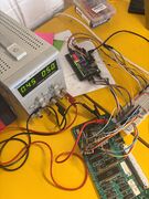
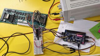
Tim hooked up his Basys fpga dev board and wanted to test the use of a 74xx245 to level shift to 3.3v so he could write a logic trace bitsteam. We saw LED's flash to test this :)


New theory: Do we have 12v? We should check (again, more carefully this time...). If we don't, it could be putting excessive load on the drive processor, as this CPU has some pins which go through a level shifter to 12v and then into a shift register (outputting at 12v).
14th April 2025 Not a meetup, just playing with the logic traces we took on the 12th. I wanted to find the most common end address from the logic traces.
# Convert all vcd files to csv
$ ls | grep vcd$ | xargs -L1 -I{} -P14 ~/git/sigrok-cli/sigrok-cli -i {} -O csv -o {}.csv

# Find the last address in each, matching a low psen line (second to last)
$ for csv in *.csv ; do tac $csv | grep '0,[01]$' | head -n1 | tr -d ',' ; done > last-addr

# Find most common end address
$ wc -l last-addr
605 last-addr
$ cat last-addr | sort | uniq -c | sort -h | tail
     26 1111011011100000
     28 0001111011100000
     38 0010111011100000
     40 0110111011100000
     43 0011000010011000
     46 1101000010011000
     48 1010111011100000
     55 1011000010011000
     62 1111000010011000
    107 0111000010011000

# Identify files which contain that binary pattern
$ cat -n last-addr | grep 0111000010011000 | tail -n3
   594	0111000010011000
   595	0111000010011000
   600	0111000010011000
$ for csv in *.csv  ; do echo "$csv" ; done | cat -n | grep -P '600\t'
   600	rom-trace-95.vcd.csv
The entry 01110000100110 (flip) decodes to address 0x190e. This is an instruction pretty early on after startup, i.e. after the reset line, so it's probably more commonly occurring because that point the glasgow's buffer is full. A useless detour
18th April 2025
It was a very intense day of LaserDisc debugging.


Notably, we made a few realisations / discoveries / etc:
- The CPU is still executing instructions up until the watchdog resets it. This was found by monitoring the PSEN, and separately address 0, while triggering off the reset line. We know that it has stopped outputting the window signal though, meaning it's asking to be reset?
- The DRIVE processor does have external RAM. 128 bytes of it, provided by the second I/O port expander.
Additionally, we got:
- A large number of traces showing various I/O activity on pins going to the CPU. These include:
- CL-RAD, which never reaches a point of changing - likely because there's no disk.
- LDI, which is pulsed 180 times after startup
- ATN, doesn't change. This goes to the Manchester Decoder
- TX/RX, also doesn't change, and also goes to the Manchester Decoder
- STB, also doesn't change and also goes to the Manchester Decoder
- IQR, which is an input, and doesn't get triggered.
- VR, which comes from the slave source, and is raised every 20ms or so.
- A larger number of traces of the first I/O expander - we've not parsed these yet.
- A much longer trace, thanks to Tim and his FPGA, showing the addresses of execution for 100,000 instructions. This is helpful!
- From this we can see that one of the functions is jumping back to 0x0000, because of something - otherwise it would continue on from where it left of. This function is at 0x072f. This may be because the state of some register is not set correctly. Lots of poking about required.
21st April 2025
Well, we did some things today.
- Got some more logic traces, some with more regions collapsed.
- Tim noticed something odd with the memory initialisation - it should only happen 128 times, but after a soft reset (i.e. jumping to 0x000), the loop continues endlessly.
- Tested the power supply some more
- While doing this, popped a fuse. Temporarily replaced 3.15 amp fuse with a 2.5 amp fuse.
- Confirmed voltage rails were stable while providing a 500mA load on the 5v rail.
Feeling suspicious. Next time we will:
- Monitor power rails from the back of the power supply during start up
- Try replacing the 27C128 ROM (which contains the drive control software)
- How do EPROMS degrade? Do they become slow before deleting everything?
- There are a number of cases in our I/O Expander traces, which mostly just logged ROM accesses, where bits are not in sync.
- Tim wants to try running the drive processor with the control processor disconnected.
- This is because the control processor is likely the thing turning other stuff on, which could be responsible for power blips.
23rd April 2025
- We replaced the 27c128 ROM with a 28c256 ROM - the high address sits on what would be the Vpp pin, meaning the second half of the 256 ROM was being used. This did not change the behaviour.
- We removed the control processor and its ROM to see what would happen - very much the same, nothing when pressing eject / standby, but the light was green. The front LED is controlled by the control processor.
- Another read was taken of the control processor ROM, it seems better now, so holding the paperclip in place lead to a ROM which was repeated, as the broken leg was the highest address.
We did not monitor the power rails from where they get distributed to the rest of the system, we'll save that for next time.
26th April 2025
We mostly focussed on measuring the voltage rails at various points in the player to see how wirespread the CPU noise was. It was slightly visible back at the power supply, but maybe it was acceptable for the era.
Started to ponder whether another chip may be getting enabled during the initial run after a watchdog/power-on reset, i.e. after the internal memory initialisation. Perhaps that chip is doing something weird to the datalines. Next time we should monitor the address lines, and data or various chip select / output enable lines.
4th May 2025
-
 The setup
 -
 Intense hacking
 -
 Probing


A big day of LaserDisc hacking. We got logic traces from several points of the following pins:
LA pin, CPU pin, name
0 39 A0/D0
1 38 A1/D1
2 37 A2/D2
3 36 A3/D3
4 35 A4/D4
5 34 A5/D5
6 33 A6/D6
7 32 A7/D7
8 21 A8
9 22 A9
10 23 A10
11 24 A11
12 25 A12
13 26 A13
14 29 !PSEN
15 30 ALE
16 16 !WR
17 17 !RE
18  x watchdog
these were taken using Tim's fpga. moop wrote a script to trace what the CPU was doing (latching the ROM address and instruction where appropriate).
- Confirmed (again) that it gets stuck in the loop after it gives up and jumps back to 0x0000.
- moop came up with a good explanation as to why:
- This would explain it getting stuck. The loop won't run less times if we're using a different bank it will never terminate.
- The loop at 190b doesn't write the a zero to bytes 127 through 0, it writes 127 through 1. We exit the loop when R0 becomes 0.
- If we're in bank 0 this means we write everything down to the R0 we're using and then stop. The DJNZ leaves a 0 in bank 0 R0 anyway.
- If we're not in bank 0 we stomp R0 with the MOV instruction instead of letting DJNZ decrement it to zero. Then DJNZ decrements it from zero.It wraps around to 255 and jumps back to the MOV which starts again from 255. It will never terminate because it's stomping its own counter register and DJNZ never sees the transition to zero!
- (context: apparently the 8051/8031 has four register banks which can be switched between and these are mapped into the internal ram starting at 0x00. Something that happens before that loop switches to register bank 2)
next:
- need to figure out why it would give up from that function (0x072f)
- maybe we can modify the ROM to help with this
A few days after, Aaron manually ran through the vr timing check function using two values for the timer register. These were 20ms (correct) and 18.25ms (what we're seeing). You can find this on subpage /Check VR Timing Function Execution
11th May 2025
Interesting day. We confirmed that the oscillator going into the SAA1043 was 5MHz, and adjusted it way out of spec (to 4.6MHz) until the timing of v-slave and h-slave was correct. This allowed the drive processor to boot, and allowed the eject to work as well as attempt to spin up a disc.
It's likely that with its own oscillator being so far off spec, the SAA1043 was unable to PLL onto the disc's frequency, which made the drive do weird things. A new chip has been ordered for experimentation, and possibly as a replacement.
Aaron's notes from the day:

v-slave header goes to pin 20   - 18.3mS - should be 20mS
-                      pin 24   - 58.0uS - should be 64uS

(/ 20 18.3) 1.0928961748633879
(/ 64 58.0) 1.103448275862069

Adjusted to 4.6MHz - V-SLAVE and H-SLAVE were corrected.
This is quite far off.
Drive span up, and kept trying to go faster.

7061 / SAA1043
For PAL:
   FD 0 (maybe 1, for PAL-M?) - Pin 7  (appears Low)
   X  1 - Pin 5  (appears High)
   Y  1 - Pin 6  (appears High)

So the configuration of the chip is correct.

We put it back to 5MHz
17th May 2025
- We replaced the SAA1043 chip (in a socket this time!), but to our surprise nothing changed, maybe.
- Measuring with the oscilloscope seemed to load the oscillator enough that it would start working.
- We replaced the 82pF loading capacitor with a similar value. The original was measuring 120pF (maybe... measuring small values is hard).
- Anyway, the drive loads the disk, but does the same weird thing as before where it tries to lock onto a track, gets to the end of a disc, and then goes crazy and spins the disc as fast as it can.
- We tried to get the diagnostics menu back, but couldn't. Aaron decided to fiddle with the sync variable resistor (towards top right of the A board photo). The TV locked on, and started displaying the diagnostics.
- Cannot remember the error code it gave.
- Contrast and brightness way off. Need to hunt down potentially dodgy electrolytic nearby.
24th May 2025
- Replaced many of the capacitors responsible for the video encoding on the A board. Diagnostics text is slightly more readable.
- Started to investigated the error reported by diagnostics. I think this was 43, but relates to the
RAD MIRRORsignal. The pulses are present, but this should be ORd with another signal,SP-POS. While this is centred at 2.5ish volts (as depicted in the schematics), it appears to be DC with almost no AC.- The
SP-POSsignal comes from the B board. - Given that
CL-RADappears ok (the CPU monitors this), we suspect there may be an issue in the "limiter". It would be good to monitor the radial mirror actuator signals, which are also on this board.
- The
Next time:
- Using the photos we took, make a map of the pads on the back of the board so that we can monitor the radial mirror actuator signals, and see at what point the signal appears to disappear.
26th May 2025


We followed the SP-POS signal back through the op-amps and believe the issue is with 7100 (schematic B). We have removed it, added a socket, and tested with a TL08. The signal is now present, but not of the correct amplitude. Unfortunately MC34002BP are unobtainium, but we have purchased three MC34002P. There's a slight difference in sensitivity (maybe this just comes from chip grading after manufacture). Something for next time :)
Update: It looks like only half of 7101 is being used. We may be able to swap 7100 and 7101, as the broken would not be in use in 7101's place. Worth a try!
Next time:
- Try a MC34002P. If that doesn't work:
- Socket and swap 7101
31st May 2025
- We tried the new chip but still ran into issues. We decided instead to swap 7100 and 7101. This is possible since the working broken half of 7100 would not be used when used in place of 7101.
- We got a nice signal on the output of 7100.
- Signal lost after darlington array to drive the radial mirror coil.
- Suspect 7012 to be bad due to forward or reverse voltage drop of 0.3v (can't remember which), which does not match the NPN equivilent 7013. Tim has ordered new transistors. Promising!
14th June 2025
- We replaced the 7012 and 7013 transistors on the B board with identical new ones
- There is a signal to the 7101-2A op-amp that looks good (40ms pulse), and we can trace it from the output of the transistors to the input of the op-amp.
- The output from this op-amp is non-existent, it is possible to just about make out the pulse on the output but it could just be crosstalk and noise, it is not as clean as the service manual suggests it ought to be.
- We tried various replacement op-amps but no effect which is confusing. We would expect even the wrong model of op-amp to output something, but none did.
- We even tried lifting the output pin so that nothing else was drawing on it, but we still didn't detect any usable signal.
- We tried adding an additional 33nF capacitor in parallel with the existing one between pins 1 and 2, no change.
- We must remember to remove it
- We tried various replacement op-amps but no effect which is confusing. We would expect even the wrong model of op-amp to output something, but none did.
22nd June 2025
- We obtained some of the correct spec op-amps, MC34002BP, and put them in place
- The situation is now worse. There isn't even a good signal going into the op-amps (out of the transistor network), where there previously was.