Sagar Chisel Mortiser: Difference between revisions
No edit summary |
|||
| Line 72: | Line 72: | ||
=== Setup === | === Setup === | ||
If the size of chisel required is not currently installed, you may need to change the tooling at this point. If the chisel is too small and only one or two mortises are to be cut, it may be more sensible to cut the mortise as long one side, then re-align the chisel and work the opposite side; where mortises of intermediate width between two chisel sizes are to be cut, this is the only method available. | |||
# Ensure the machine is switched off. | |||
# Approximately centre the table. | |||
# Raise the lever to bring the chisel clear of the bed. (N.B. Lifting the lever to vertical will result in the rack disengaging from the quadrant, allowing the mechanism to drop and potentially damaging it. '''Never lift the lever up completely vertical.''') | |||
# Place the work flat on the table and close the vice. | |||
# Lower the lever until the tip of the auger is just above the work. | |||
# Line up the edge of the chisel with the edges of the marked area (It may be necessary to use a small Set-Square placed on the workpiece to assist.) | |||
# If making a stub mortise, bring the lever down until the cutting lip of the auger touches the workpiece, and bring the depth stop down in contact with the workpiece, mark this position, then raise the depth stop up by the desired amount, using the mark to measure from, and secure the depth stop with the set-screw. | |||
=== Machining === | === Machining === | ||
Revision as of 23:19, 27 August 2016
Purchased by a pledge drive, and currently being installed in the workshop.
About the Machine

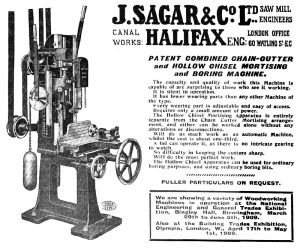
Manufactured by J. Sagar & Co. Halifax, based on promotional materials it appears to be based on a design already in production by 1909, and subsequently re-designed in the late 20's to run on electrical rather than overhead belt power, living history right here in the hackspace no less.
What does it do?
Put simply, it is a drill for square holes.
More comprehensively, A hollow chisel mortiser has a auger bit running inside a hollow, square chisel. Pulling the lever down brings the auger into the wood, cutting away the bulk of the material, before the chisel follows 1/16" behind, taking away the material in the corners to give a square hole.
Why do we want to do that?

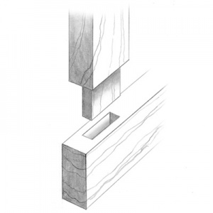
Mortise and Tenon joints in all their many forms, remain the strongest and most secure method of joining two pieces of wood.
Cutting a tight-fitting hole, in a piece of wood, which is dead square in all three dimensions, using nothing more than a mallet and chisel, requires a substantial amount of skill and practice;[1] not to mention a reasonable amount of effort; by contrast a chisel mortiser allows all this to be done with little more than a push of a button, turn of a wheel and pull of a lever.[2]
It's hoped that this will open up some more ambitious and structural woodworking projects to all comers.[3]
Installation Progress
The machine is now in position, but inoperative until the power is connected.
The bolt which secures the chisel in position, unfortunately seized and subsequently sheered on attempting to free it. The remainder of the bolt has been drilled out, the residue of the threads removed with a tap, and a replacement (and spare) set-screw of the appropriate size (5/16 Whitworth) has been sourced.
Parts sourced:
- 2 × 5/16 BSW 2½" allen head set screws
Parts on order:
- 12m of 5 core, 2.5mm2 armoured cable.
- 20A rotary isolator.
- 440v DOL Motor Starter, with 1.8-2.5A thermal overload.
Parts to order:
- ½ or ¾ ply - 2'6" by 8" — sacrificial table top.
- New tooling.
Costs:
| Item | Qty. | Price per each | Total cost | Running total |
|---|---|---|---|---|
| # Morticer | 1 | £80.00 | £80.00 | £80.00 |
| Van Hire | 1 | £95.00 | £95.00 | £175.00 |
| Fuel | 1 | £20.03 | £20.03 | £195.03 |
| BSW Bolts | 2 | £1.50 | £3.00 | £198.03 |
| 3 Ph Cable | 12m | £2.78 | £33.36 | £231.39 |
| Isolator | 1 | £11.50 | £11.50 | £242.89 |
| DOL Starter | 1 | £35.49 | £35.49 | £278.38 |
Standard Operating Procedure
First select dimensions and layout of the joints, appropriate to the timbers to be joined.
Layout
- On each piece to be mortised, determine a "reference face" and mark it lightly in pencil.
- Prepare a "rod"
- Take a piece of scrap timber, ply or MDF, with at least one straight edge, and cut one end perpendicular to the straight edge.
- Using a sharp, dark pencil and a steel rule or combination square, make marks at the following distances: reference face to near side of mortise, reference face to far side of mortise, end of timber to beginning of mortise, end of timber to end of mortise and (if required) end of timber to end of haunch.
- Use the rod to make marks on each piece indicating the distances.
- Using a Set-Square or Combination Square join these marks to form a rectangle indicating material to be removed.
- Cross hatch the area to be removed
Setup
If the size of chisel required is not currently installed, you may need to change the tooling at this point. If the chisel is too small and only one or two mortises are to be cut, it may be more sensible to cut the mortise as long one side, then re-align the chisel and work the opposite side; where mortises of intermediate width between two chisel sizes are to be cut, this is the only method available.
- Ensure the machine is switched off.
- Approximately centre the table.
- Raise the lever to bring the chisel clear of the bed. (N.B. Lifting the lever to vertical will result in the rack disengaging from the quadrant, allowing the mechanism to drop and potentially damaging it. Never lift the lever up completely vertical.)
- Place the work flat on the table and close the vice.
- Lower the lever until the tip of the auger is just above the work.
- Line up the edge of the chisel with the edges of the marked area (It may be necessary to use a small Set-Square placed on the workpiece to assist.)
- If making a stub mortise, bring the lever down until the cutting lip of the auger touches the workpiece, and bring the depth stop down in contact with the workpiece, mark this position, then raise the depth stop up by the desired amount, using the mark to measure from, and secure the depth stop with the set-screw.
Machining
Tool Change Procedure
Wiring Diagram
Footnotes
- Indeed, it is not enough to develop the skill once, regular practice is essential to continue making a good job of it.
- The keen eyed reader will note that in the above advertisment, Sagar suggest that being usable by "a lad" was one of the machine's selling points.
- Especially the author, who always enjoys mortising by hand to begin with, before getting part-way through and realising that He's ultimately rather lazy.