BigClocks

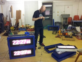
Nottinghack have several Old Station radio clocks, we have also passed clocks on to Leeds Hackspace, London Hackspace, Build Brighton, Northackton and HacMan in Manchester.
This page is to detail our combined efforts into reverse engineering these clocks to allow something a little more interesting than just the time to be display on the huge LCD panels
Quick details
- Each clock is double sided.
- Each panel is made up of two AEG GV60 lcd panels http://www.aegmis.de/
- There are 2 PIC17XXXXXX chips on the base electronics board ('RepRap' Matt i suspect each 1 is driving an LCD panel)
- Theres is a NEC D70320GJ on what appears to be the main logic board
- 128Byte UV erasable EPROM chip next to NEC chip
- Might also be a 128k Ram chip
Arduino library
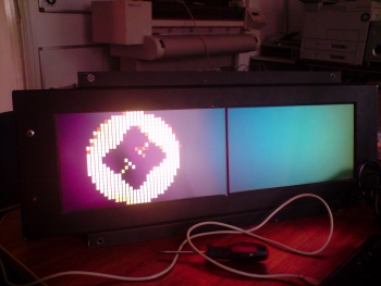
An Arduino can be used drive the display instead of the existing controller, by using this library.

The library is a bit of mess at the moment, to say the least (although it does work!), and expects to put in the same library folder as the 'timer1' library. It also includes an example program which scrolls the H logo across the display.
It expects to be connected to the first buffer board as follows:
    +-----+-----+
D6  |  1  |  2  | +5v
D6  |  3  |  4  | ~1v - use 10k POT between 3v3 and GND
N/C |  5  |  6  | +5v
N/C |  7  |  8  | 3v3
N/C |  9  | 10  | +5v
D4  | 11  | 12  | +5v
N/C | 13  | 14  | D2
D11 | 15  | 16  | GND
N/C | 17  | 18  | GND
D13 | 19  | 20  | GND
    +-----+-----+
(Pin numbers relate to the 20pin IDC connector going from the controller to the buffer board).
Some notes on what the pins on the output of the original controller seem to be used for:
| Pin | Description |
|---|---|
| 1 | Some kind of constant square wave for board 0. Exact frequency doesn't seem too critical, but it needs to be there |
| 2 | 5v to panel |
| 3 | Same 1, but for board 1. Seems to work fine with the same signal shared between the boards - although the signals from the original controller are out of sync between the boards. |
| 4 | Contrast? I've connected a (i think) 10k pot between 3v3 and GND, with the wiper connected to this pin, then adjusted until "it looked right". |
| 5 | Data return from board 0. |
| 6 | 5v to panel |
| 7 | Data return from board 1 |
| 8 | 3v3 to panels |
| 9 | latch / strobe for board 0. Briefly goes low (or was it high?) to separate the data between each panel |
| 10 | 5v for board logic |
| 11 | Same as 9, but for board 1 |
| 12 | 5v for board logic |
| 13 | Data for board 0 |
| 14 | +v5. This is also board select - it controls if the board is 0 or 1 (i.e. which set of pins it gets its input from). It's high going into the first board, which inverts it before passing it on to the second. I've cheated and used this so I can get away with only driving one set of clk/data/strobe pins, and then flipping this pin (it's the cause of the tearing when scrolling :/). The original controller outputs to both boards simultaneously (presumably the reason for the two PIC chips). |
| 15 | Same as 13, but for board 1 |
| 16 | GND |
| 17 | Clock for board 0 |
| 18 | GND |
| 19 | Clock for board 1 |
| 20 | GND |
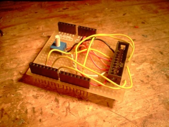
If anyone wants a play with this, I've put a 20-pin IDC connector on an Arduino shield and wired it up appropriately you're welcome to borrow (Daniel 15:24, 7 August 2012 (EST)):
Leeds Hackspace Investigations
http://leedshackspace.org.uk/projects-2/brunell-station-clocks/
Northackton Investigations
http://northackton.stdin.co.uk/wiki/BigClock
London Hackspace Investigations
http://wiki.london.hackspace.org.uk/view/Project:Infotec_displays
