Superbox CNC Router/Maintenance
Replacing the Spindle Fuse
On several occasions, the spindle fuse has blown. If this is the case, there will be an audible relay noise clicking in the control box when the spindle is turned on through G-Code but nothing will happen at the spindle.
The procedure to replace the fuse is fairly simple. In the video shown below the fuse used is: T3.15A 250V.
Fuses are kept upstairs in the workshop, see the set of narrow wooden draws on the floor to the right side of the wall of boxes.
Squaring the CNC
Why does the CNC need to be square?
In order for a CNC to cut objects accurately, the X and Y axes must be as perpendicular as possible to each other. Otherwise, if you try and cut a rectangle, it will actually end up as a parallelogram. Even a small misalignment between the axes can lead to issues. These are particularly noticeable when cutting double-sided or large parts.
The Homing Sequence in Y
The Superbox CNC Router has a dual Y axis stepper setup. Each of these Y steppers (called joints in LinuxCNC configuration) has their own homing switch.
The linuxCNC configuration files are located at /home/nottinghack/linuxcnc/configs/Superbox2.8. The file of interest for autosquaring (and general configuration) is SuperBox2.8.ini.
The Y axis contains [JOINT_1] and [JOINT_2]:
    [JOINT_1] is labelled as 'Y' on the controller, and is the Right Y axis joint.
    [JOINT_2] is labelled as 'A' on the controller, and is the Left Y axis joint.
In this file, there are two parameters which effect the movement of each of these joints, and the axis. These are 'HOME_OFFSET' and 'HOME', and are defined separately for each joint in the axis.
When the Y axis is homed, both steppers (joints) move the gantry towards the inductive homing switches, and when the homing switches are triggered, that position is defined as the HOME_OFFSET. Think of the HOME_OFFSET as us telling the CNC where the joint is actually located after hitting the homing switch. The switch is hit on one side of of the gantry, and the gantry stops on that side, and now knows where it is. That position is the HOME_OFFSET.
Let's say the HOME_OFFSET for both joints is 355mm. When the homing switch is hit at each end of the gantry, each joint knows its position is 355mm from the origin.
The next parameter is HOME. This tells the joints their home position, which is the position they move to after homing. For the Superbox CNC, HOME is 345mm. This means that after hitting the homing switch, the joints both back off by -10mm (towards 0), as 345-355 = -10mm.
We also define a MIN_LIMIT and MIN_LIMIT for each joint (and indeed, the axis as a whole). In this case, for the Superbox CNC, the min limit for Y is 0mm and the MAX limit is 350mm. This means that, after the homing sequence above, where each joint backs off -10mm from the homing switch and that position is set as 345mm in Y, the CNC is allowed to move -345mm before it hits 0, and +5mm before it hits 350mm. In this way, we've defined the work area of the CNC in Y.
Note that HOMING_SEQUENCE is set as '-2' for both Y joints. The number '2' being shared by both joints causes them to home simultaneously, and defines the order (Z is 0 and X is 1, so Y homes last). Counterintuitively, -2 doesn't home first, rather the minus sign indicates that the first joint to home will wait for the other before moving to HOME together
Autosquaring through modification of the homing sequence
The fact that each joint has its own HOME_OFFSET allows us to set each joint to a different position after the homing switches are hit. After both joints have hit the homing switches, they both proceed to the HOME position together. Let's say HOME for both joints remains the same as before, 345mm, and the HOME_OFFSET for the left joint remains as before, at 355mm. This means, as above, that when the left joint hits the homing switch it will back off by -10mm (345-355 = -10).
Now, what happens if we set the HOME_OFFSET of the right joint to 351.7153mm? Repeat the above calculation for the new value: 345 - 351.7153 = -6.7153mm.
So, the left Y joint moves back 10mm from the homing switch, and set its position as 345mm. The right Y joint moves back 6.7153mm from the homing switch, and set its position as 345mm. The effect of this is a warping of the gantry. One side of the gantry moving 3.2847mm further than the other might seem a large change, but the separation between the steppers is 600mm, and the gantry will flex to accommodate this change.
Once we figure out how out of square the X and Y axes are, we can use the HOME_OFFSET of the right Y joint to manipulate the position of either end of the gantry, bringing the CNC back into square.
(The '-' modifier in HOME_SEQUENCE = -2 should now make more sense. If one joint didn't wait for the other one to reach the homing switch before moving to home, then one side of the gantry would still be moving slowly towards the limit switch, while the other side quickly moves towards HOME. The CNC could therefore be damaged if HOME_SEQUENCE = -2 was not set and the gap in time between the homing switches being hit at either end of the gantry was too large.)
Squaring Procedure
The Pythagorean theorem relates the lengths of the legs, (a, b) of a triangle, to the hypotenuse, c. If we go to a position, such as X=0, Y=350, we can make a mark using a pen attached to the Z axis onto the sticky section of a post-it note or masking tape stuck onto the T-slot bed. We can then move a defined distance in X and Y, and make another mark, for example at position X=270.066, Y=0. By doing this, we are tracing two sides of a right-angled triangle, where a (Y) and b (X) are equal to 350mm and 270.066mm respectively.
If the CNC is square, this should be a right-angled triangle, as the X and Y axes should be perfectly perpendicular to each other. using Pythagoras, we can work out what the diagonal measurement between the points should be, which is 442.08mm.
If we measure the length between the points made with the pen, and get this figure, great! The CNC is already square. Bear in mind that even measuring a single millimetre off should be corrected. Let's say we measure a value of 443.25mm, where the hypotenuse is 1.17mm longer than it should be.
If the actual measurement is under this value of 442.08mm, this means that this triangle is not a right-angled triangle, but instead the angle between X and Y is less than 90 degrees. Likewise, if the actual measurement exceeds 442.08mm, then the angle between X and Y exceeds 90 degrees. Both of these situations require correction. So, just from our measured value of 443.25mm, we can tell that the angle opposite the hypotenuse of the triangle must exceed 90 degrees.
This gives us a more understandable value of how out of square the CNC is. In this case, we obtain an angle of 90.314 degrees.
We can use more trigonometry to relate this angle to the offset between the joints, and provide a correction.
Subtracting this angle from 90 degrees gives us another value, in this case -0.314 degrees (if the γ angle opposite the hypotenuse was greater than 90, then this value would instead be positive).
This angle of -0.314 degrees forms the bottom-left corner of a right-angled triangle that represents the position of the Y steppers relative to each other. The long edge of this triangle is the separation between the steppers, which is 600mm for the Superbox CNC. We want to determine the length opposite this angle of -0.314 degrees, which we can do using the Rule of Sines.
The α angle is -0.314, the β angle is 90, and the b side is 600mm. The answer is -3.29mm, which is the answer to the question if the left joint is at 0mm, where is the right joint?, and is the squaring offset that we set out to find. (note that the Google calculator above won't accept -0.314 as an input, instead requiring you to use 0.314mm instead, giving an answer of 3.29mm. You can either use another calculator, or just add the negative sign onto the final answer).
Applying the Squaring Offset in LinuxCNC
We discussed above how changing the HOME_OFFSET on the right Y Joint will manipulate the gantry.
If we add this value of -3.29mm to the HOME_OFFSET of 355mm, we get a value of 351.71mm. This is our new home offset for the right Y Joint. No other values are changed in LinuxCNC. The worked example in the 'Autosquaring through modification of the homing sequence' section uses this value of 351.71mm for the right Y joint, and therefore squares the gantry. Save the ini file, restart LinuxCNC and home the CNC. The changes should be applied.
Note that the adjustments made should only be relatively small (and indeed should only ever need to be!). As stated, HOME is at 345mm, and the default HOME_OFFSET is 355mm, causing the CNC to back off from the homing switches by 10mm, and 5mm from Y MAX. If the HOME_OFFSET for the right Y joint is decreased more than 5mm, after homing, Y_MAX will be less than 5mm from the inductive limit switch. If the HOME_OFFSET is reduced by more that 10mm, Y_MAX will be behind the limit switch, and it will be triggered during normal operation of the CNC. This is not desirable. The same issue applies to an increase in the HOME_OFFSET, which could cause one end of the gantry to collide with the aluminium extrusion just below Y=0.
In the event of the squaring requiring a change in the HOME_OFFSET +-5mm away from 355mm (aka below 350mm or above 360mm), which might occur after a crash, for example, the CNC should be squared mechanically first, before performing the above steps. If the offset to apply remains large, you may consider these options:
Applying an inverse offset to the other joint. An offset +-7mm might be more safely managed by moving one end of the gantry 3.5mm less in one direction, and another 3.5mm more in the other. Reducing the work area through manipulation of Y_MAX, HOME and HOME_OFFSETs.
Confirming the Squaring Worked
Repeat the above squaring process after rehoming the CNC, and see if the measured length of the hypotenuse is such that the triangle is now right-angled. The formulae above should work perfectly, but fine adjustments can be made.
Full worked example
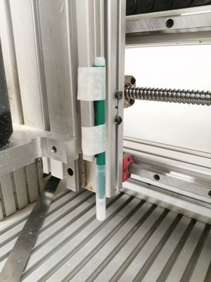
First, mount a felt tip pen to the Z axis. Runout is not important (as measurements are relative), only that the pen can reach the T-Slot bed, and that the pen doesn't move during measurements. I attached the pen to the right-hand side of the Z Axis, in a little groove, using masking tape.

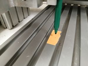
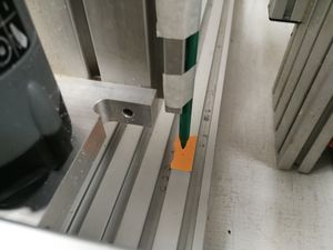
I then moved the CNC to X=0, Y=350, which happened not not be over a T-Slot. We're aiming to draw the largest triangle for the highest accuracy, so we're starting in the top-left. I then moved the Z axis down, until I could see well enough where the pen was going to land to place half the sticky section of a post-it note underneath. Masking tape would also be a good choice for this.
I then moved Z down until the pen tip was nearly touching. We're aiming for the smallest possible dot for accuracy, so don't being the pen down too far, or leave it down for too long. A quick 0.5mm (or even 0.1mm) drop onto the paper, followed by a quick retraction should make a suitable mark. In the image shown, I probably could've made the dot a little smaller.

We then go all the way down to Y=0, and then across as far as possible to a suitable location. I ended up at Y=0, X=270.066. Repeat the process from above to make another mark.

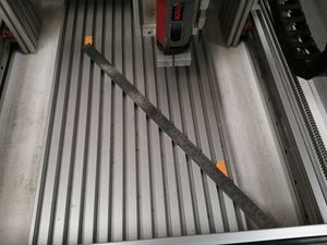
Now, move the CNC back -Y to get the gantry out of the way, and simply measure the distance between the two points. I used a 60cm metal ruler from metalworking for this, as the 1m ruler was too long to fit in the CNC at the angle I needed.

This is my squaring calculator for the Superbox CNC, which can be copied and edited.
I inputted these four values into the calculator:
    Input Distance X, 270.066mm
    Input Distance Y, 350mm
    Measured diagonal (Hypotenuse), 443.25mm
The calculator outputted a calculated offset of -3.29mm (if the left joint is at 0mm, where is the right joint?) and a Calculated RIGHT Y Joint (JOINT_1) HOME_OFFSET of 351.7153mm. Noting that this offset value of -3.29mm isn't massive (I would be worried if this value was much over 5mm), I inputted it into SuperBox2.8.ini, located at /home/nottinghack/linuxcnc/configs/Superbox2.8 as the value for HOME_OFFSET, under the header #Y Joint [JOINT_1]
I then restarted LinuxCNC, and homed the CNC (home all joints). I then repeated the above steps, and measured a new hypotenuse of 442mm that seemed to be perfect for the input lengths of X=270, Y=350, confirming that the squaring procedure was successful.
Additional Resources
A good Video on CNC Squaring:
(In this video, he manually moves the limit switches, but we accomplish the same result using HOME_OFFSET in software.)