Talk:Cheesoid: Difference between revisions
Jump to navigation
Jump to search
No edit summary |
limit height of code areas |
||
| Line 39: | Line 39: | ||
OK, motors tested with a two motor circuit... | OK, motors tested with a two motor circuit... | ||
<syntaxhighlight lang="cpp" line="GESHI_FANCY_LINE_NUMBERS"> | |||
<!-- <div style ="height:200px;overflow-x:hidden;overflow-y:auto;width: auto;border: 2px solid black;"> --> | |||
<div style ="height:200px;overflow-x:hidden;overflow-y:auto;border: 4px solid green;"> | |||
'''Motor Test sketch (non-PWM)''' | |||
<syntaxhighlight lang="cpp" line="GESHI_FANCY_LINE_NUMBERS" enclose="div"> | |||
int motor_left[] = { | int motor_left[] = { | ||
2, 3}; | 2, 3}; | ||
| Line 166: | Line 170: | ||
} | } | ||
</syntaxhighlight> | </syntaxhighlight> | ||
</div> | |||
This sketch is a munge of http://letsmakerobots.com/node/2074 and http://itp.nyu.edu/physcomp/Labs/DCMotorControl | This sketch is a munge of http://letsmakerobots.com/node/2074 and http://itp.nyu.edu/physcomp/Labs/DCMotorControl | ||
Revision as of 18:30, 28 September 2011
- interact with the fridge for cheese status
- interact with the petrol pump for petrol status
- it needs to know where they are to go and talk to them
- the status needs to be stored and needs to be set - Xino at each?
- it need to be able to read the status from the fridge and the petrol pump - what sort of interface? IR remote control?
Petrol status
- just a number!
Cheese status
- many cheese types - each with use by date
- Primula status is "in tube"
Motor skills
- get motors from post office - DONE
- simple test circuits with 12V battery and driver ICs
- Texas Instruments L293NE or Texas Instruments SN754410 (almost equivalent)
- useful searches L293NE or SN754410 PWM arduino
- http://itp.nyu.edu/physcomp/Labs/DCMotorControl
- http://www.ti.com/product/sn754410
- datasheet: http://www.sparkfun.com/datasheets/IC/SN754410.pdf
- PWM for speed control - a two motor library perhaps with feedback loop via rotary encoder?
- using PWM on 2 motors http://letsmakerobots.com/node/2074
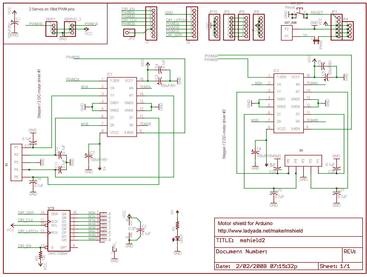
- Adafruit motor shield is a good example:
- http://www.adafruit.com/products/81
- http://www.ladyada.net/images/mshield/mshieldv1-schem.png
- My own custom motor shield for 2 DC motors
- mounting the motors and designing the axle couplings
- building the wheels : nearly done - some tweaking and securing to do
- building the plastic chassis - what's that display board plastic material called?
- milling the plastic
- strong enough to carry those batteries? !!!!
- aluminium cross bracing?
- battery mount - where?
- perhaps move to 2x 6V - keep it flexible
- battery regulation: http://letsmakerobots.com/node/3880
OK, motors tested with a two motor circuit...
This sketch is a munge of http://letsmakerobots.com/node/2074 and http://itp.nyu.edu/physcomp/Labs/DCMotorControl
I want to have motor enable based on digital logic as this will be controlled by bumper and cliff sensors
Range Sensors
- SRF05 by Devantech Ltd
Xino upgrades
- power screw terminal blocks: http://uk.rs-online.com/web/p/products/4258720/
- smt caps for smt regulators!
PIN usage on main Xino
- PWM capable pins: 3,5,6,9,10,11
- Dig out x2 for eyes
- Dig in for mode switch
- dig out for beacon on pin 13
- motor enable dig out
- PWM x4 for motor logic control - can it be reduced?
- bumper and cliff inputs - use serial mux?
- others!
PIN usage summary table...
TODO
goal/job list
Take to HS:
- boxfile, eeepc, station clock antenna, wheel assemblies,
- big battery station? nah,
- backup multimeter and hook probes - label it and solder plugs onto probe wires
DO: -
- camp in blue room with all gear
- fabricate chassis
- 40mm al angle motor mounts
- al cross support plates
- wheel assemblies
- pizza box mods
- power port extension
- USB extension - USB hub
- PWR switch extension - LED in "Micro", PWR switch? Monostable/bistable startup flasher circuit for "Micro" switch
- cylinder case mods
- speakers in mouth plate/grill
- side mount for Xino and boards
- top for beacon - keep on side for now
- mounting of cylinder on pizza box
- Xino/UNO main sketch code
- motor drive code and motor drive commands from PC
- speech commands from
- PC app code
- console read and process
- speech module
- speech commands from stdin
- speech thread - busy flag and job queue management
- motor module
- motor control input from STDIN
- sensor module
- camera module - look at Java interaction with V4L or whatever is in use
- mic input - and speech recognition
- GUI interface port and GUI app
--Michael Erskine 11:38, 28 September 2011 (EST)