Project:Line-following Robot: Difference between revisions
No edit summary |
m Fowkc moved page Line-following Robot to Project:Line-following Robot |
||
| (4 intermediate revisions by one other user not shown) | |||
| Line 3: | Line 3: | ||
((insert video here!)) | ((insert video here!)) | ||
Original photos at https://plus.google.com/photos/101627167067307203883/albums/5758095721560984897 | |||
(( | ((upload process takes too long from the wiki so this is in progress)) | ||
I want to now move the circuit off my Arduino Uno with breadboard and onto a Xino with a "micro-shield". What's a micro-shield? It's a ghetto Arduino shield that uses just a few of the pins and can be knocked together cheaply with a few scraps of stripboard and pins. | I want to now move the circuit off my Arduino Uno with breadboard and onto a Xino with a "micro-shield". What's a micro-shield? It's a ghetto Arduino shield that uses just a few of the pins and can be knocked together cheaply with a few scraps of stripboard and pins. | ||
[[File: | [[File:Line-follow-micro-shield-001.png|none|400px|A micro-shield base]] | ||
I found this tiny bit of spripboard that was 12x4 holes but nicely separated down the middle... | I found this tiny bit of spripboard that was 12x4 holes but nicely separated down the middle... | ||
[[ | [[File:Line-follow-micro-shield-002.png|none|A micro-shield base]] | ||
I have loads of male header pins (we have boxes of them at Hackspace and I also get them from work) and here I'm using 7 pins that fit in digital pins 8, 9, 10, 11, 12, 13, and the ground pin. That gives me access to 3 digital pins with PWM and 3 without | I have loads of male header pins (we have boxes of them at Hackspace and I also get them from work) and here I'm using 7 pins that fit in digital pins 8, 9, 10, 11, 12, 13, and the ground pin. That gives me access to 3 digital pins with PWM and 3 without. | ||
The line-follower robot requires two PWM pins to drive the motors via a mosfet... | The line-follower robot requires two PWM pins to drive the motors via a mosfet. Here's a little circuit diagram I jotted down to help me with wiring... | ||
[[File:Line-follow-micro-shield-003.png|none|A micro-shield base]] | |||
I mounted the two mosfets with drain pins to a common ground linked to the GND pin... | I mounted the two mosfets with drain pins to a common ground linked to the GND pin... | ||
[[File:Line-follow-micro-shield-005.png|none|A micro-shield base]] | |||
I don't want to solder my motor wires on as I want to swap them between projects so I have two header pins per motor connection, slightly bent outwards, one pin goes to source on the mosfet and one pin goes to +5v... | I don't want to solder my motor wires on as I want to swap them between projects so I have two header pins per motor connection, slightly bent outwards, one pin goes to source on the mosfet and one pin goes to +5v... | ||
I'm using jumpers as little F-F connectors (a little trick I developed to save on expensive female headers)... | [[File:Line-follow-micro-shield-006.png|none|A micro-shield base]] | ||
I'm using jumpers as little F-F connectors (a little trick I developed to save on expensive female headers - I have hundreds of jumpers knocking around)... | |||
[[File:Line-follow-micro-shield-007.png|none|A micro-shield base]] | |||
The mosfets need gate connections (middle pin) to the PWM pins to switch on the motors... | The mosfets need gate connections (middle pin) to the PWM pins to switch on the motors... | ||
We also have a little jumper wire to go to the 5v pin on the other side of the Arduino... | [[File:Line-follow-micro-shield-008.png|none|A micro-shield base]] | ||
We also have a little jumper wire (in red) to go to the 5v pin on the other side of the Arduino and 5v supplies to the other end of each motor... | |||
[[File:Line-follow-micro-shield-009.png|none|A micro-shield base]] | |||
Now, we also need a header for the Light Dependent Resistor (LDR), an LED to normalise any ambient light, and a calibration pushbutton... | |||
((TODO: LDR, LED, and pushbutton mounts. Software. Mounting on the Xino. New robot design. LDR/LED nose structure.)) | |||
Latest revision as of 00:53, 12 June 2014
As part of the Arduino 102 (or is it 201?) we built line-following robots...
((insert video here!))
Original photos at https://plus.google.com/photos/101627167067307203883/albums/5758095721560984897 ((upload process takes too long from the wiki so this is in progress))
I want to now move the circuit off my Arduino Uno with breadboard and onto a Xino with a "micro-shield". What's a micro-shield? It's a ghetto Arduino shield that uses just a few of the pins and can be knocked together cheaply with a few scraps of stripboard and pins.
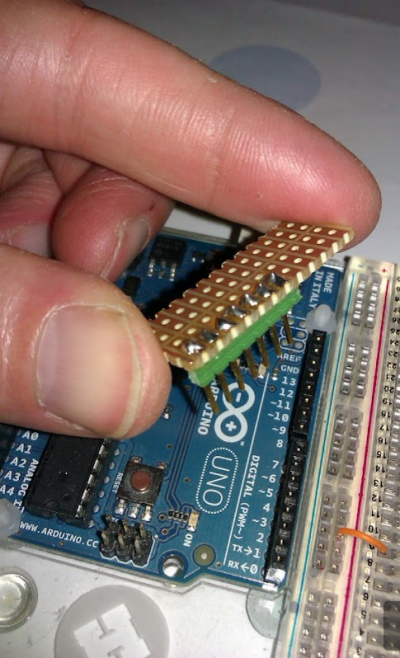
I found this tiny bit of spripboard that was 12x4 holes but nicely separated down the middle...
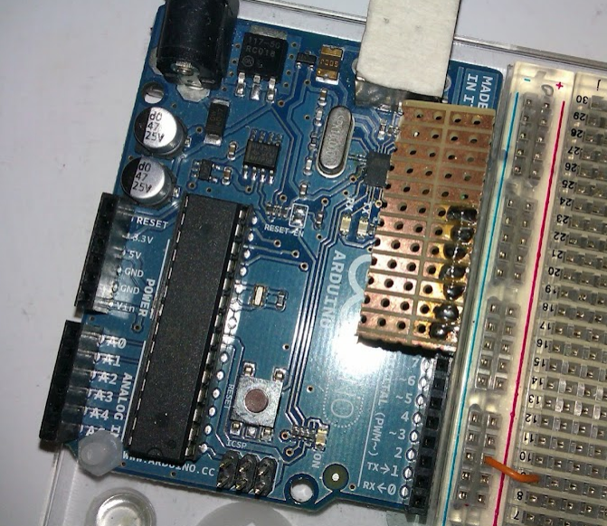
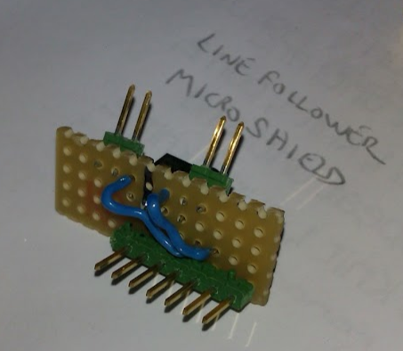
I have loads of male header pins (we have boxes of them at Hackspace and I also get them from work) and here I'm using 7 pins that fit in digital pins 8, 9, 10, 11, 12, 13, and the ground pin. That gives me access to 3 digital pins with PWM and 3 without.
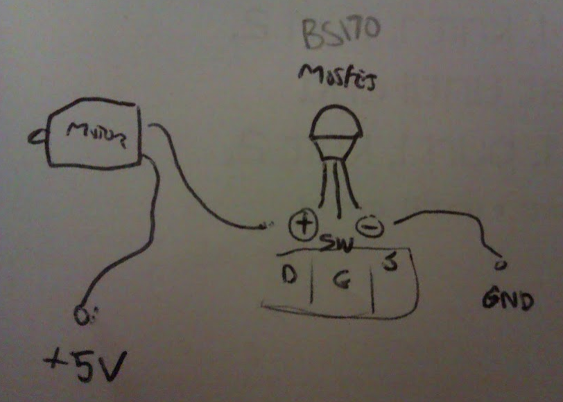
The line-follower robot requires two PWM pins to drive the motors via a mosfet. Here's a little circuit diagram I jotted down to help me with wiring...
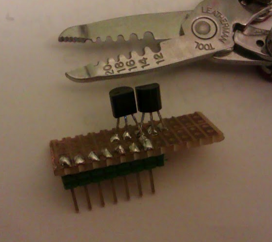
I mounted the two mosfets with drain pins to a common ground linked to the GND pin...
I don't want to solder my motor wires on as I want to swap them between projects so I have two header pins per motor connection, slightly bent outwards, one pin goes to source on the mosfet and one pin goes to +5v...
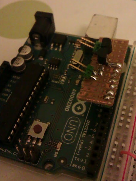
I'm using jumpers as little F-F connectors (a little trick I developed to save on expensive female headers - I have hundreds of jumpers knocking around)...
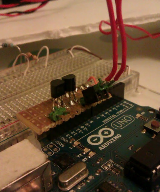
The mosfets need gate connections (middle pin) to the PWM pins to switch on the motors...
We also have a little jumper wire (in red) to go to the 5v pin on the other side of the Arduino and 5v supplies to the other end of each motor...
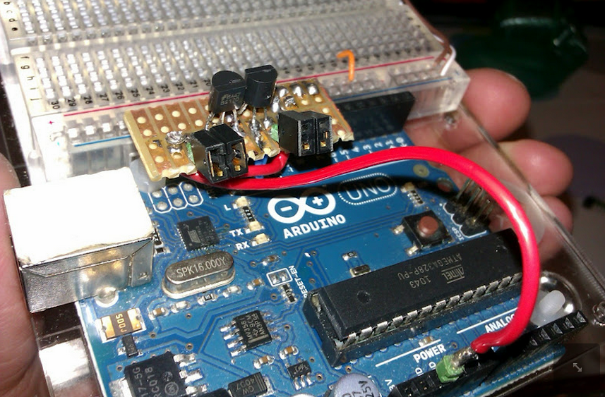
Now, we also need a header for the Light Dependent Resistor (LDR), an LED to normalise any ambient light, and a calibration pushbutton...
((TODO: LDR, LED, and pushbutton mounts. Software. Mounting on the Xino. New robot design. LDR/LED nose structure.))