Lighting Automation: Difference between revisions
m Danspencer101 moved page Project:Lighting Automation to Lighting Automation over redirect |
m →Switches: "look out, here comes an S" |
||
| Line 35: | Line 35: | ||
The 12vdc relays will be ordered from rapid code 60-0905, along with appropriate MOSFET's<br/> | The 12vdc relays will be ordered from rapid code 60-0905, along with appropriate MOSFET's<br/> | ||
===[[Lighting Automation/Switch| | ===[[Lighting Automation/Switch|Switches]]=== | ||
Two main switch panels and various smaller control points will be mounted around the space<br/> | Two main switch panels and various smaller control points will be mounted around the space.<br/> | ||
Two larger panels, one in the workshop and one by the last man out switch in the comfy area.<br /> | Two larger panels, one in the workshop and one by the last man out switch in the comfy area.<br /> | ||
The two large panels will be custom laser etched | The two large panels will be custom laser etched boxes with plan view maps of the hackspace, each lighting zone will have a momentary push switch, possible lit when the lights are out<br/> | ||
Again for control in the large panels we will use | Again for control in the large panels we will use Xinos and Wiznet shields<br /> | ||
Each panel will need a 5v power supply and network connection | Each panel will need a 5v power supply and network connection | ||
Smaller 1 or 2 button switch | Smaller 1 or 2 button switch boxes will be mounted in the following areas. | ||
* Textiles room | * Textiles room | ||
* Between the kitchen & toilets | * Between the kitchen & toilets | ||
| Line 49: | Line 49: | ||
* Members box room | * Members box room | ||
* Hall way | * Hall way | ||
The smaller switches will be build from | The smaller switches will be build from XRFs possible with a ATtiny2313, but only if it can't be done in LLAP firmware on the XRFs<br/> | ||
These will only need a 5v power supply as communication will be done over the existing LLAP<>MQTT bridge<br/> | These will only need a 5v power supply as communication will be done over the existing LLAP<>MQTT bridge<br/> | ||
Revision as of 22:42, 11 February 2019
| Lighting Automation | |
|---|---|
 | |
| Primary Contact | Team:Infrastructure |
| Created | 26/04/2012 |
| Dormant | 12/12/2014 |
| Status | Dormant |
| Type | Hackspace Infrastructure |
The Problem
The existing lighting in the hackspace is a real mess.
Switching is all over the place and its hard to get hold of replacement tubes for the massive fittings.
The current lighting is split across 9 switches/zones.
The Fix
This summers big hackspace infrastructure project is to rewire the lighting throughout the whole space.
Of course being a hackspace we are adding our own techno touch to this job :)
Thanks to an unnamed member we have a growing stock of second hand fittings that will be used to replace the existing 8ft fittings.
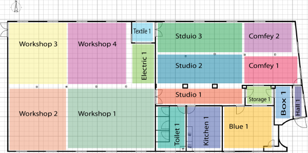
The plan to rewire also includes a move to better zoning of the lights and will call for 17 zones over the existing 9.
This quick plan shows the various zone that will be individually controllable
The Tech
Now being a hackspace good old fashioned light switches are just not going to cut it.
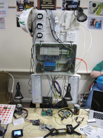
So it was suggested that we could build an integrated system by having the lights wired back to central control boards, fitted with contractors and relays.
These relays can of course be switched by an Arduino or other micro and giving us ultimate control over the hackspace lights.
The Light switches around the hackspace will be replaced with micro's and pushbuttons
Having micro's in the systems means we can easily do multi-way switching and not just from custom control board's but also from webpages or mobile apps
The Plan

The 17 zones will be split across two control box's, 7 to a board in the workshop and 10 to a board in the members storage room.
Control Box
Each control box will house contactor's, relays and a networked micro-controller.
A contactor is a 240v electrically controlled switch, like a relay but for much higher current
Each contactor is switched via a 12vdc relay, which in turn is switched via an arduino and MOSFET setup
5vdc Relays would remove the need for the MOSFET but they are much harder to acquire and cost a lot more
Micro-controller in each control board is likely to be a Xino (arduino clone) and a Wiznet Ethernet shield
Again thanks to generous donations we have 17 contactor's and relay holders already at the space.
The 12vdc relays will be ordered from rapid code 60-0905, along with appropriate MOSFET's
Switches
Two main switch panels and various smaller control points will be mounted around the space.
Two larger panels, one in the workshop and one by the last man out switch in the comfy area.
The two large panels will be custom laser etched boxes with plan view maps of the hackspace, each lighting zone will have a momentary push switch, possible lit when the lights are out
Again for control in the large panels we will use Xinos and Wiznet shields
Each panel will need a 5v power supply and network connection
Smaller 1 or 2 button switch boxes will be mounted in the following areas.
- Textiles room
- Between the kitchen & toilets
- Blue room
- Member storage room
- Members box room
- Hall way
The smaller switches will be build from XRFs possible with a ATtiny2313, but only if it can't be done in LLAP firmware on the XRFs
These will only need a 5v power supply as communication will be done over the existing LLAP<>MQTT bridge
Light Fittings
After the control box's and the wire runs are in place the job of swapping the light fittings over will begin, most of the 8ft's will be replaced with 5ft fittings and tube's.
There will be a call for help when we get round to this stage.
Wire Runs
Heavy feeds will be run from the distribution boards to the new control boards and then wire runs from the control board to each zones first light will be added.
Runs between fitting may be reused from the old lighting if appropriate.
Control Software
Of course getting all this to talk is going to need several bits of firmware and a possible controller process on Holly
Basic idea is the switch panels will send an MQTT message say toggle a zone, the controllers will then update the zone and publish back the new state
See the Control Software page for more details on how this works.
Firmware is on GitHub
https://github.com/NottingHack/Lighting-Control
Backup System
Just in case there will be old fashioned override switches located near each of the control box's
Cool ideas
The system will include an ambient light sensor to detect if its dark outside, this will be used to automatically turn certain light's on.
If its dark the hallway light will turn on for 5 minutes any time either of the doors is opened.
On entering the closed space from the hallway, the walkway lights (comfy area & studio) between the last man switch and the workshop will automatically turn on.
On closing the space (last man out switch) and light left on will be automatically turned off.
A web page interface can't be built into the hackspace intranet site.
Mobile phone app
Toilet lights can be on a 30minute(adjustable) timer so they don't get left on.
