Nhtools: Difference between revisions
m →Hardware: - PCB |
|||
| Line 12: | Line 12: | ||
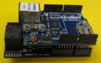
The current device on the [[Laser cutter]] is a prototype, built on an Arduino UNO (or clone, I can't remember), wiznet based Ethernet shield and [http://shop.ciseco.co.uk/protox-standard-worlds-best-prototype-shield-for-xino-and-all-arduino-type-boards/ protoshield]. The next version will be built using a custom PCB, see [https://github.com/NottingHack/NH-Tool-PCB GitHub] for the design. | The current device on the [[Laser cutter]] is a prototype, built on an Arduino UNO (or clone, I can't remember), wiznet based Ethernet shield and [http://shop.ciseco.co.uk/protox-standard-worlds-best-prototype-shield-for-xino-and-all-arduino-type-boards/ protoshield]. The next version will be built using a custom PCB, see [https://github.com/NottingHack/NH-Tool-PCB GitHub] for the design. | ||
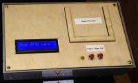
[[File:tools_laser.jpg|200px|thumb|right|tool control prototype on laser cutter]] | [[File:tools_laser.jpg|200px|thumb|right|tool control prototype on laser cutter]] | ||
[[File:tools_pcb1.jpg|200px|thumb|right|Next version of tools control device]] | |||
The RFID reader is a MFRC-522 based device purchased from hobby components ([http://hobbycomponents.com/index.php/rfid-module-kit-mifare.html HCMODU0016]) and connected using SPI, the LCD is a 2x16 I2C display also from Hobby Components ([http://hobbycomponents.com/index.php/arduino-compatible-iic-i2c-twi-ywrobot-serial-lcd-1602-module.html HCARDU0023]). | The RFID reader is a MFRC-522 based device purchased from hobby components ([http://hobbycomponents.com/index.php/rfid-module-kit-mifare.html HCMODU0016]) and connected using SPI, the LCD is a 2x16 I2C display also from Hobby Components ([http://hobbycomponents.com/index.php/arduino-compatible-iic-i2c-twi-ywrobot-serial-lcd-1602-module.html HCARDU0023]). | ||
Revision as of 22:22, 21 November 2014
The tools access control device (which still needs to be named) is designed to allow use of the attached tool to be restricted to inducted members, and to keep track of usage for charging purposes. It's been designed with the aim of being easy to fit to multiple different tools if needed (e.g. lathe and mill), not just the laser cutter - although charging for use is unlikely to be used for other tools.
For the Laser cutter, it keeps track of pledged time, and charges by the second for those that didn't pledge, or have used up their pledged time. Any laser usage which isn't covered by pledged time is charged in the same way as the Vending machine, which results in a monthly email, and can be paid off using either the Snackspace jar, or the NoteAcceptor.
The hardware consists of an Arduino, Ethernet shield, RFID module, (optional) LCD and relay, and it communicates with a server side process on Holly using MQTT, specifically an instance of the Mosquitto MQTT broker.

There is a related tool booking system running on HMS, however the interaction with that is limited; booking a tool in HMS currently has no connection to who can or can't sign on to the laser. HMS can be used by any member to see their use of the laser (and any charges as a result), as well as see if the laser is currently in use or not.
Hardware
The current device on the Laser cutter is a prototype, built on an Arduino UNO (or clone, I can't remember), wiznet based Ethernet shield and protoshield. The next version will be built using a custom PCB, see GitHub for the design.


The RFID reader is a MFRC-522 based device purchased from hobby components (HCMODU0016) and connected using SPI, the LCD is a 2x16 I2C display also from Hobby Components (HCARDU0023).
The attached tool is controlled by using a relay on the protoshield - this is intended more for isolation, and not to switch any great load. In the case of the laser cutter, the relay on the protoshield is wired back to another relay+contactor inside the laser cutter which is wired in series with the incoming mains. There are two push buttons; one to allow authorised members to record other members as having been inducted, and one to sign off. There is also a status LED that lights up when the signed in member is authorized to give inductions, and flashes after the induct button had been pressed and the system is searching for a card to induct (the original idea was that the induct button would be an illuminated push button).
| Pin | Description |
|---|---|
| A4 | SDA for LCD |
| A5 | SCL for LCD |
| D2 | Sign off button |
| D3 | Induct button |
| D4 | (Used by Ethernet shield?) |
| D5 | Relay |
| D6 | RFID RST |
| D7 | RFID Slave Select (labelled SDA on RFID module) |
| D8 | Sign off LED. Currently unconnected - but will be used for tools that don't have an LCD |
| D9 | Induct LED |
| D10 | (Used by Ethernet shield?) |
| D11 | MISO for RFID & Ethernet |
| D12 | MOSI for RFID & Ethernet |
| D13 | SCK for RFID and Ethernet |
Firmware
The source code for the Arduino firmware is on GitHub,
The Arduino firmware uses these libraries:
- PubSubClient - https://github.com/knolleary/pubsubclient - for MQTT communications
- HCARDU0023_LiquidCrystal_I2C_V2_1 - http://forum.hobbycomponents.com/viewtopic.php?f=39&t=1125 - for the I2C LCD
- rfid - https://github.com/miguelbalboa/rfid - RFID reader
The firmware includes a serial based setup menu to configure MAC/IP addresses, set the MQTT topic and tool name; these settings are stored in EEPROM. The idea is to be able to set up the device for another tool without having to change any code.

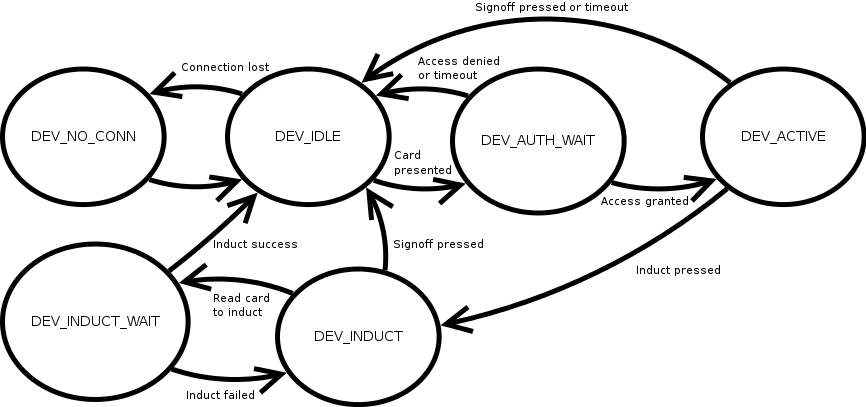
The device can be in one of 6 states (valid transitions shown in the diagram), these are:
| State | Description |
|---|---|
| DEV_NO_CON | No network and/or MQTT connection |
| DEV_IDLE | Connected to MQTT broker on Holly, tool not being used, waiting for an RFID card to be scanned. |
| DEV_AUTH_WAIT | An RFID card has been scanned, and a lookup request sent over the network |
| DEV_ACTIVE | Tool access enabled. It is not possible to leave this state with whilst the RFID card is still on the reader (e.g. pressing the sign out button does nothing with the card still present, nor does a loss of network connection); the only exception is if the induct button is pressed and the signed on member is authorised to induct others. |
| DEV_INDUCT | The induct button has been pressed and the currently signed on member is permitted to give inductions. The device starts looking for any RFID card other than the one used to sign on. |
| DEV_INDUCT_WAIT | A second RFID card has been found, and a request to induct the member sent. |
Communications
All communications with the server side is done using MQTT; topic names are comprised of "<base topic><tool name>/<command>". Base topic can be the same for all access controlled tools, but obviously the name must be unique. The base topic currently being used is "nh/tools/", and the name set for the laser cutter is "laser".
| Direction (A=Arduino, S=Server) | Command | Payload | Description |
|---|---|---|---|
| A > S | AUTH | <RFID Serial> | Sent to the server when a card is first presented |
| S > A | GRANT | <U/I/M><16 char message>\n<16 char message>
|
The first character must be either U, I or M, which corresponds to the access levels User, Induct or Maintain. Currently there is no difference in the firmware between I and M - both will allow the signed on member to induct others. The remainder of the payload is displayed on the LCD, with a newline character expected to split text for the top and bottom line. At the moment for the laser cutter, the first line shows the username, and the second the amount of pledged time remaining (or blank if none). After 5 seconds, the bottom line of the LCD is wiped and replaced with a session timer (hh:mm:ss).
Once this command is received, power to the tool is enabled. |
| S > A | DENY | <16 character message> | Received in response to an AUTH if the RFID card was rejected - the message in the payload is displayed on the first line of the LCD. Possible reasons at the moment include "Out of credit", "Unknown card".... |
| A > S | COMPLETE | <tool active time> | Sent once either the sign off button is pressed, or the 15s card timeout is reached. The payload is currently always 0, but in the future may be the amount of time the laser tube is active for (there is no hardware or firmware support for this yet). |
| A > S | INDUCT | <induct RFID>:<inductee RFID>
|
Sent when the induct button has been pressed, and a second RFID card found. |
| S > A | ISUC | User inducted successfully; device returns to idle state | |
| S > A | IFAL | <16 char message> | Induct failed. the payload is the failure reason, and is displayed on the first line of the display. Possible reasons include "Bad card", "Not a member". If received, the device looks for another card to try again. |
| A > S | RESET | BOOT / ACTIVE / IDLE
|
|
Examples
Normal sign on with ~10 hours pledged time remaining, then sign off:
< [nh/tools/laser/AUTH], message=[1234567890]
> [nh/tools/laser/GRANT], message=[UFoo
Remain  10:02:16]
< [nh/tools/laser/COMPLETE], message=[0]
Member "Bar" with RFID "0000000001" signing on, then successfully inducting member with RFID "9999999999":
< [nh/tools/laser/AUTH], message=[0000000001]
> [nh/tools/laser/GRANT], message=[IBar
Remain  12:07:53]
< [nh/tools/laser/COMPLETE], message=[0]
< [nh/tools/laser/INDUCT], message=[0000000001:9999999999]
> [nh/tools/laser/ISUC], message=[]
Configuration
The device has a serial based configuration menu (9600 baud, set local echo on) which can be used to set:
- MAC address
- IP address
- Tool name - e.g. "laser"
- Base topic - e.g. "nh/tools"
The IP address of the server is currently hard-coded to be 192.168.0.1 (Holly), this should probably be added to the configuration menu at some point. Once set, these settings are saved in EEPROM. E.g. showing current settings:
Main menu
---------
[ 1 ] Show current settings
[ 2 ] Set MAC address
[ 3 ] Set IP address
[ 4 ] Set name
[ 5 ] Set base topic
[ 6 ] Reset/reboot
Enter selection: 1

Current settings:
MAC address: 12:23:34:45:56:67
IP address : 192.0.2.1
Name       : test
Base topic : nh/tools
Note that the device must be reset after changing any of these settings - option 6 will reset the Arduino by abusing the watchdog timer.
TODO
- Allow server IP address to be set using serial config menu
- Tidy up RFID code (remove duplication), and allow the type of RFID reader to be changed relatively easily
Current issues
The biggest problem at the moment is interference from the TIG welder. This either causes the RFID reader to stop reading cards (causing a time-out and sign-off after 15 seconds), or causes the Arduino to reboot, which one happens seems to vary, but obviously neither is good!
There are also issues with the RFID reader not reading some cards - in particular some newer oyster cards. This is probably down to the choice of RFID reader.
Software
The server side component runs on Holly, is part of the Instrumentation project, and is responsible for authorising members to sign on / induct others, keeping track of pledged time and billing for time used. The source code is on GitHub.
TODO: Add some details.