Talk:Cheesoid
Interaction Goals
Cheesoid is intended to be a fully autonomous mobile robot that interacts with people and objects in its environment. Human-Robot interaction is a massive subject but I intend to get some rudimentary (and comedic) speech and general input features in place as soon as possible. The environment interactions will develop as I learn more about sensing and mapping. Since the robot will live at Hackspace I have two basic goals for comedy value: -
- interact with the fridge for cheese status
- interact with the petrol pump for petrol status
So...
- it needs to know where they are to go and talk to them
- the status needs to be stored and needs to be set - Xino at each? Via IRC bot? Some web interface?
- it need to be able to read the status from the fridge and the petrol pump - what sort of interface? IR remote control?
Petrol status
- just a number!
Cheese status
- many cheese types - each with use by date
- Primula status is "in tube"
Human - Robot Interactions: speech
With the eeePC I have a very capable processor on board and I'm taking full advantage of that: -
- using espeak for text to speech
- using sphinx for speech recognition
Text to Speech with espeak
http://espeak.sourceforge.net/
The espeak voices aren't really robotic enough but can be made more so by creating a custom voice
speech recognition with sphinx
http://cmusphinx.sourceforge.net/wiki/tutorialconcepts
The sphinx packages
p    --\ sphinx2-bin                                                                                                                    <none>     0.6-2.1
  Description: speech recognition utilities
    Sphinx 2 is a real-time, speaker-independent speech recognition system.

    This package contains examples and utilities that use Sphinx. It also includes a sample language model that is capable of recognizing simple commands
    like "go forward ten meters" and other commands one might use to tell a robot where to move.
  Priority: optional
  Section: universe/sound
  Maintainer: Ubuntu MOTU Developers <ubuntu-motu@lists.ubuntu.com>
  Compressed size: 129k
  Uncompressed size: 500k
  Source Package: sphinx2
  --\ Depends (3)
    --- libc6 (>= 2.4)
    --- libsphinx2g0 (>= 0.6) (UNSATISFIED)
    --- sphinx2-hmm-6k (UNSATISFIED)
  --\ Packages which depend on sphinx2-bin (0)
  --\ Versions of sphinx2-bin (1)
p    0.6-2.1
Good examples of the use of sphinx: -
If Sphinx 4 works on the eeePC (try the demos) then go ahead and use it from Java.
Conversations and dialogue
In order to have a meaningful (preferably amusing and slightly uncanny) interaction with humans there needs to be a dialogue and some involvement of non-verbal communications: perhaps some shared experience, empathy, etc. We can fake a lot of things to push the human participant closer to the goal!
- New status phrases (with equivalents and random or circular selection) - use emotional terms
- "I don't know where I am"
- "I'm not happy"
- "I'm scared"
- "I'm upset"
- "this is all wrong" - "I don't like this situation"
- "what is this place?"
- "where am I? I can't see and I can't move"
- "I haven't been here before"
- "I need to check the petrol but I can't get there"
- "I need to check the cheese but I can't get there"
- "I can't move. Someone will have to carry me"
- "I'm very lonely. Can somebody talk to me" (on IRC/or actual voice)
- "There's nothing here"
- "This is terrible. Is there no god?"
- Wake up phrases for Map module...
- "Do I know this place?"
- "Is this [location name]?"
- "Can somebody tell me where I am?"
Mobility
- motors
- wheels
- chassis
- motor power
- motor control circuitry
- big battery
Drive motors: I now have my 12V 150RPM gearmotors from China
- simple test circuits with 12V battery and driver ICs
- Texas Instruments L293NE or Texas Instruments SN754410 (almost equivalent)
- useful searches L293NE or SN754410 PWM arduino
- http://itp.nyu.edu/physcomp/Labs/DCMotorControl
- http://www.ti.com/product/sn754410
- datasheet: http://www.sparkfun.com/datasheets/IC/SN754410.pdf
- PWM for speed control - a two motor library perhaps with feedback loop via rotary encoder?
- using PWM on 2 motors http://letsmakerobots.com/node/2074
- Adafruit motor shield is a good example:
- http://www.adafruit.com/products/81
- http://www.ladyada.net/images/mshield/mshieldv1-schem.png
- My own custom motor shield for 2 DC motors
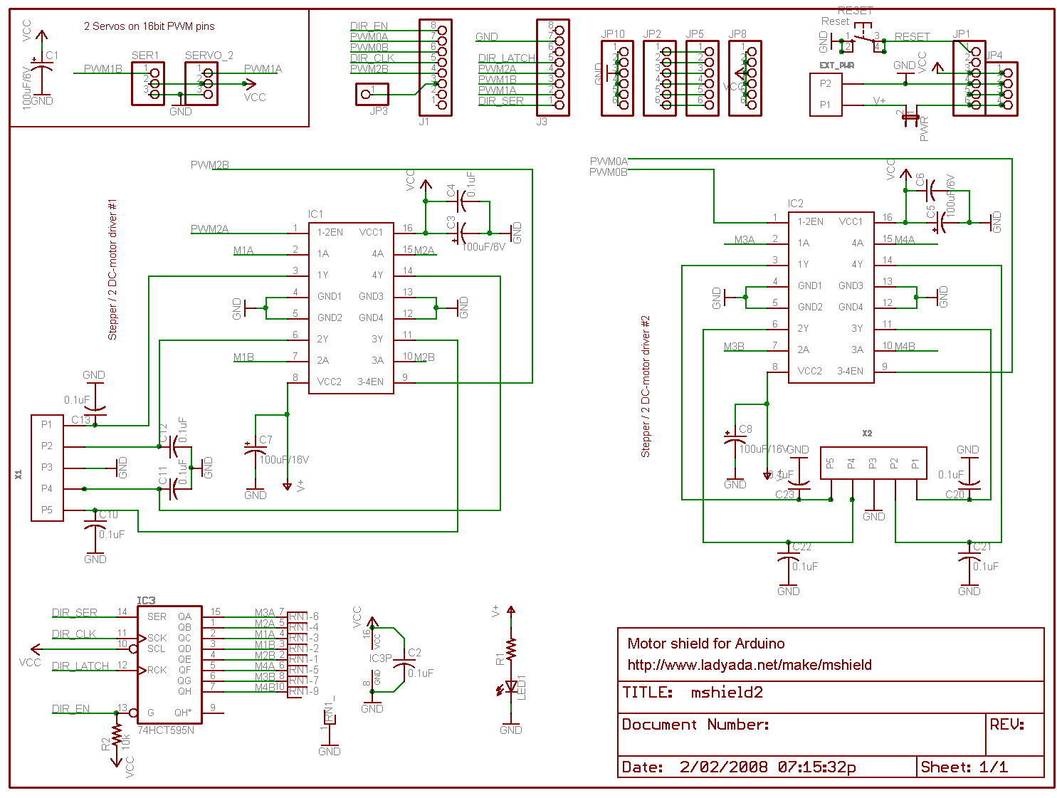
OK, motors tested with a two motor circuit...
This sketch is a munge of http://letsmakerobots.com/node/2074 and http://itp.nyu.edu/physcomp/Labs/DCMotorControl
OK, after a couple of nights at Hackspace I now have the motors mounted and coupled to the wheel assemblies but the whole thing is way too weak to drive the wheels when using the big 12v lead-acid batteries I have. It's a little better with the bench power supply at 12v and it's how I'd want it with the bench supply at 14v. I think there's multiple problems here: the wheel assemblies are heavy and the shed-built motor brackets are inaccurate, as are the polymorph couplings (an idea borrowed from here http://letsmakerobots.com/node/15354). I thought that the wheel assembly would be necessary to take some of the load off the motor axles but I see quite a lot of setups with the wheels attached directly to the motors as in this example that also uses 38mm motors: http://www.pololu.com/catalog/product/730
I'm tempted to redesign around some direct wheel couplings and purchased wheels even though I love the CD wheel idea.
- http://www.active-robots.com/2-x-universal-hub-6mm-shaft.html
- http://www.active-robots.com/motors-wheels/motor-hardware/dc-motor-hardware/2-x-pololu-universal-hub-6mm-shaft.html
- http://www.skpang.co.uk/catalog/pololu-universal-aluminum-mounting-hub-for-6mm-shaft-pair-p-800.html
I've joined the letsmakerobots.com forum and I'm going to ask some advice there.
--Michael Erskine 09:18, 8 October 2011 (EST)
MCU1 Motor Control
MCU1 will drive each motor via the SN754410 with three signals: Motor_Logic_1, Motor_Logic_2, and Motor_Enable (corresponding to the SN754410 pins). The Motor_Enable signals will be PWM thus using in total 2 PWM outputs plus 4 digital outputs. This allows a simple interface to the SN754410.
Control is via serial from the eeePC giving parameters of direction and speed for both motors at once. The motors can be put in hold with a stop command. The messages need to be quick for MCU1 to read and interpret but also easily human-readable.
 D[L-dir][L-speed][R-dir][R-speed]

 direction = 1 char, 'F' = forwards, 'B' = backwards, 'X' = hold
 speed = 3 ASCII decimal digits in range 000 to 255 left zero padded
Examples: -
- DF255F255 = full speed ahead
- DF127F127 = half speed ahead
- DF000F000 = freewheel?
- DX000X000 = hold stop
- DB255F255 = fast rotate left
- DF255B255 = fast rotate right
- DX000F255 = fast pivot left
The PWM will continue unless stopped so we should have a timeout on MCU1
Bodywork
- building the plastic chassis
- what's that display board plastic material called?
- is it http://www.foamcore.com/ultra-board.html
- milling the plastic - is nicely cut with a fine jigsaw blade - try router table!
- can it be laser cut? may contain chlorine or other nasties: see http://www.nycresistor.com/2008/08/28/how-to-identify-polymers-with-burnination/
- battery regulation: http://letsmakerobots.com/node/3880
- battery mounting - where?
- chassis strong enough to carry those batteries? !!!!
- aluminium cross bracing?
- perhaps move to 2x 6V - keep it flexible
- cylinder case mods
- speakers in mouth plate/grill
- possible replacement speaker: USB rechargeable single speaker $6.38
- http://lightake.com/detail.do/sku.Audio_Artist_Hamburger_Mini_Speaker___Black-41485
- side mount for MCU1 and support boards (temporary?)
- top for beacon - keep on side for now
- mounting of cylinder on chassis -- 2x panel circular base (inner diameter of shell) cut with jigsaw
- speakers in mouth plate/grill
- pizza box - vertical holder
- motor mountings
- simple aluminium angle mountings - might make some more of these with greater accuracy!
- motor to axle couplings
- building the wheels/axles/bearing hubs: nearly done - some tweaking and securing to do
Motor shaft couplings being the most annoying thing right now
- I really need some well made couplings like these
Small hose clips may be the thing.
Brains
The current design makes use of a few processors: the small cheap eeePC 701 4G netbook and a couple of inexpensive (£7) Xino Arduino micros.
MCU1 and MCU2
Xino devices
- power screw terminal blocks: http://uk.rs-online.com/web/p/products/4258720/
- smt caps for smt regulators!
MCU1 PIN usage summary table here on Google Docs
MCU1 software
MCU2 software
- drives LCD display
- needs serial in from MCU1
- status LED to panel
eeePC mods
Hardware and system mods to support "isolated usage".
- soldered in an external power button cable
- PWR button sub-assembly with safety keyswitch - mount on side panel
- TODO LED in "Micro" and other nice illuminated buttons
- Monostable/bistable startup flasher circuit for "Micro" switch?
- "pizza box" container
- power port extension
- USB extension - USB hub - still powering MCU1 from USB - much drain?
- Lid switch: do not suspend when lid closed - instead just switch to external monitor output
- http://forum.eeeuser.com/viewtopic.php?pid=20450#p20450
- sudo nano /etc/acpi/lidbtn.sh
- Lid switch: do not suspend when lid closed - instead just switch to external monitor output
#!/bin/sh
LID_STATE=`cat /proc/acpi/button/lid/LID/state | awk '{print $2 }'`

if [ $LID_STATE = "closed" ] ; then
#    /etc/acpi/suspend2ram.sh
        /bin/su user -c "/usr/bin/xrandr --output VGA --mode 800x600 --output LVDS --off"
fi
if [ $LID_STATE = "open" ] ; then
        /bin/su user -c "/usr/bin/xrandr --output LVDS --preferred --output VGA --off"
fi
exit 0
This is not enough: the eeePC will not power on with the lid closed so I had to disable the lid closed sensor by removing the magnet from screen section of the case
- clean up and test external monitor output - not fully working with some of my external monitors
- removed EasyMode which "mostly" fixes the "are you sure" dialog for shutdown via power switch
- http://wiki.eeeuser.com/howto:useicewm#configuration_of_icewm
# minimal brightness
echo 0 > /sys/devices/platform/eeepc/backlight/eeepc/brightness"
# screen off after 2 minutes
xset dpms 0 0 120
Speaker volume
- make commands for volume up and down
- amixer set LineOut 3.20dB- unmute
- amixer set LineOut 3.20dB+ unmute
eeePC problems
- unionfs inode depletion causing "No space left on device" but df shows plenty of space!
- http://forum.eeeuser.com/viewtopic.php?pid=537876#p537876
- mount /dev/sda2 elsewhere and remove the '.wh*' files
- running out of space due to other errors ~/.Xsession-errors
- firefox won't start - oh well!
eeePC Software
- console read and process
- speech module
- speech commands from stdin
- speech thread - busy flag and job queue management
- motor module
- motor control input from STDIN
- sensor module
- camera module - look at Java interaction with V4L or whatever is in use
- mic input - and speech recognition
- GUI interface port and GUI app
One annoyance is having to open the eeePC to find out its IP address to get back in via SSH. My proposed solution is to display the eeePC wlan IP address on the LCD on MCU2.
Additionally I'll make use of some of my remote servers to track IP addresses posted by cheesoid...
- In .bash_login run the checkservice script to start the cheesoid service
- upon startup cheesoid gets its LAN IP address and uses wget to publish it
- wget http://(sitename)/mick/cheesoid-track-wgetter?(wifi-lan-IP)
Additional
Range Sensors
- SRF05 by Devantech Ltd
- IR: SHARP GP2Y0A21YK
- £10.50 from oomlout
- http://www.oomlout.co.uk/infra-red-distance-sensor-w-cable-p-229.html
- Ultrasonics have a wide beam (shape patterns usually in data sheets).
- IR tends to have a narrow beam
Wide beam in ultrasonic can help find smaller objects that the narrow if might miss if not in it direct line, IR can see wall but might miss table leg! --'RepRap' Matt 07:48, 3 November 2011 (EST)
Rotary Encoders for wheels
- an easily available "obsolete" ball type PS/2 mouse
- Microsoft "Mouse Port Compatible Mouse 2.0A"
- using the serial output from the mouse circuitry
- encoder usage in daylight
- mounting encoder wheel to axle
PIR - human sensor
Using an AirWick FreshMatic...
- http://letsmakerobots.com/node/26618
- http://outroot.com/blog/2010/01/10/airwick-motion-sensor-pir-with-an-arduino/
Original author's sketch...
My version "Smart Motion A-06" "Ver:RB-S04" "2008/08/05"
Nice usage... https://picasaweb.google.com/patyoungers/MunnyDollNightlightInfraredDetector?authkey=Gv1sRgCK7Ao_e2lZrfsgE#