Difference between revisions of "Talk:Cheesoid"
Jump to navigation
Jump to search
| Line 17: | Line 17: | ||
* get motors from post office - DONE | * get motors from post office - DONE | ||
* simple test circuits with 12V battery and driver ICs | * simple test circuits with 12V battery and driver ICs | ||
| + | ** Texas Instruments L293NE or Texas Instruments SN754410 (almost equivalent) | ||
| + | ** useful searches [http://www.google.co.uk/search?q=L293NE+or+SN754410+PWM+arduino L293NE or SN754410 PWM arduino] | ||
** http://itp.nyu.edu/physcomp/Labs/DCMotorControl | ** http://itp.nyu.edu/physcomp/Labs/DCMotorControl | ||
** http://www.ti.com/product/sn754410 | ** http://www.ti.com/product/sn754410 | ||
| Line 176: | Line 178: | ||
* power screw terminal blocks: http://uk.rs-online.com/web/p/products/4258720/ | * power screw terminal blocks: http://uk.rs-online.com/web/p/products/4258720/ | ||
* smt caps for smt regulators! | * smt caps for smt regulators! | ||
| + | |||
| + | PIN usage on main Xino | ||
| + | |||
| + | * PWM capable pins: 3,5,6,9,10,11 | ||
| + | * Dig out x2 for eyes | ||
| + | * Dig in for mode switch | ||
| + | * dig out for beacon on pin 13 | ||
| + | * motor enable dig out | ||
| + | * PWM x4 for motor logic control - can it be reduced? | ||
| + | |||
| + | PIN usage summary table... | ||
Revision as of 16:15, 28 September 2011
- interact with the fridge for cheese status
- interact with the petrol pump for petrol status
- it needs to know where they are to go and talk to them
- the status needs to be stored and needs to be set - Xino at each?
- it need to be able to read the status from the fridge and the petrol pump - what sort of interface? IR remote control?
Petrol status
- just a number!
Cheese status
- many cheese types - each with use by date
- Primula status is "in tube"
Motor skills
- get motors from post office - DONE
- simple test circuits with 12V battery and driver ICs
- Texas Instruments L293NE or Texas Instruments SN754410 (almost equivalent)
- useful searches L293NE or SN754410 PWM arduino
- http://itp.nyu.edu/physcomp/Labs/DCMotorControl
- http://www.ti.com/product/sn754410
- datasheet: http://www.sparkfun.com/datasheets/IC/SN754410.pdf
- PWM for speed control - a two motor library perhaps with feedback loop via rotary encoder?
- using PWM on 2 motors http://letsmakerobots.com/node/2074
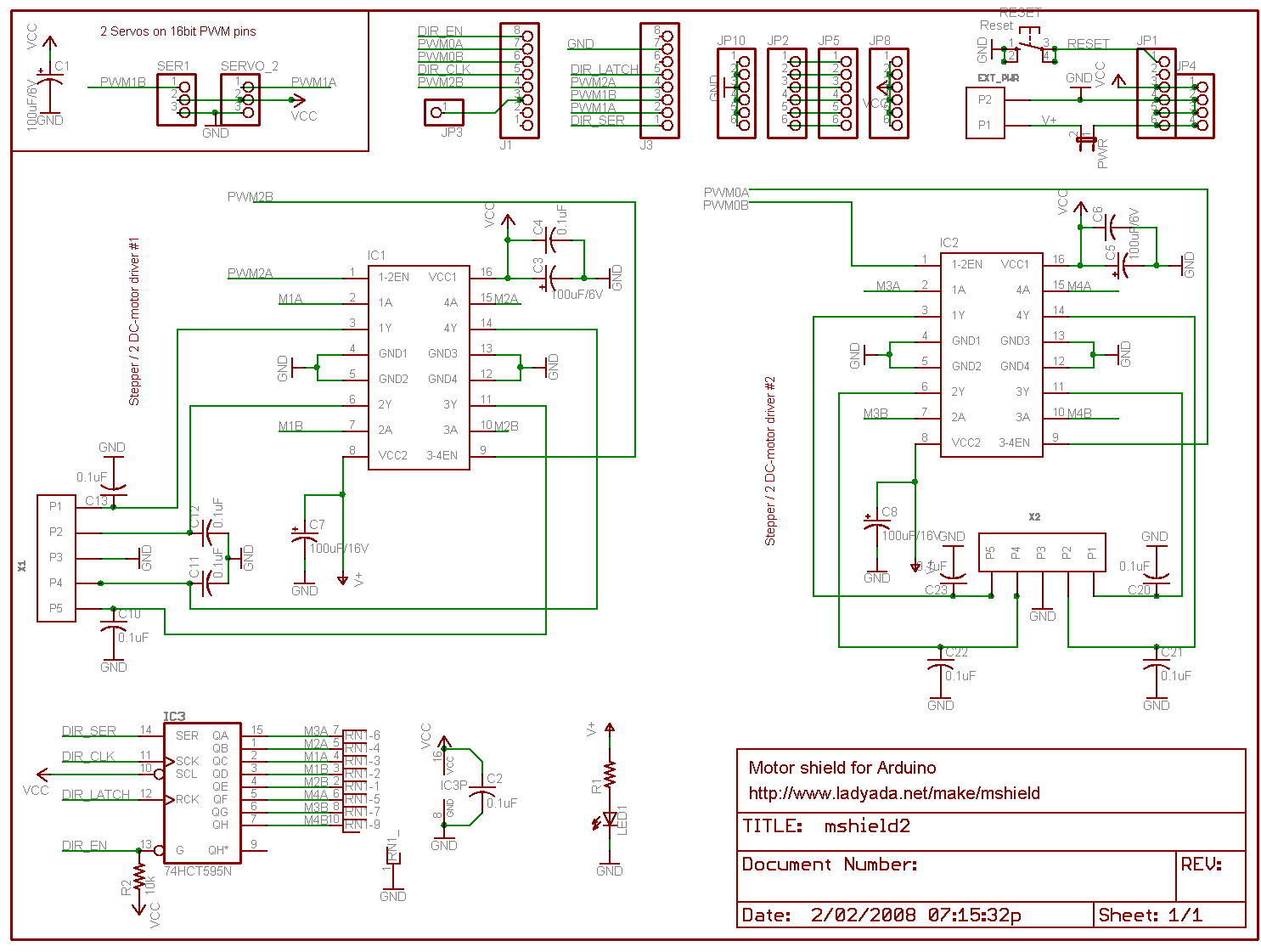
- Adafruit motor shield is a good example:
- http://www.adafruit.com/products/81
- http://www.ladyada.net/images/mshield/mshieldv1-schem.png
- My own custom motor shield for 2 DC motors
- mounting the motors and designing the axle couplings
- building the wheels : nearly done - some tweaking and securing to do
- building the plastic chassis - what's that display board plastic material called?
- milling the plastic
- strong enough to carry those batteries? !!!!
- aluminium cross bracing?
- battery mount - where?
- perhaps move to 2x 6V - keep it flexible
- battery regulation: http://letsmakerobots.com/node/3880
OK, motors tested with a two motor circuit...
  1 int motor_left[] = {
  2   2, 3};
  3 int motor_right[] = {
  4   7, 8};
  5 const int ledPin = 13;      // LED
  6 const int switchPin = 10;    // switch input
  7 const int enablePin = 9;    // H-bridge enable pin
  8
  9
 10 // ————————————————————————— Setup
 11 void setup() {
 12   Serial.begin(9600);
 13   pinMode(ledPin, OUTPUT);
 14   pinMode(switchPin, INPUT);
 15   pinMode(enablePin, OUTPUT);
 16
 17
 18   // Setup motors
 19   int i;
 20   for(i = 0; i < 2; i++){
 21     pinMode(motor_left[i], OUTPUT);
 22     pinMode(motor_right[i], OUTPUT);
 23   }
 24   check_enable();
 25   // blink the LED 3 times. This should happen only once.
 26   // if you see the LED blink three times, it means that the module
 27   // reset itself,. probably because the motor caused a brownout
 28   // or a short.
 29   blink(ledPin, 3, 100);
 30
 31 }
 32
 33
 34 void check_enable(){
 35   digitalWrite(enablePin, digitalRead(switchPin));
 36 }
 37 // ————————————————————————— Loop
 38 void loop() {
 39
 40   drive_forward();
 41   delay(1000);
 42   motor_stop();
 43   Serial.println("1");
 44
 45   drive_backward();
 46   delay(1000);
 47   motor_stop();
 48   Serial.println("2");
 49
 50   turn_left();
 51   delay(1000);
 52   motor_stop();
 53   Serial.println("3");
 54
 55   turn_right();
 56   delay(1000);
 57   motor_stop();
 58   Serial.println("4");
 59
 60   motor_stop();
 61   delay(1000);
 62   motor_stop();
 63   Serial.println("5");
 64 }
 65
 66 // ————————————————————————— Drive
 67
 68 void motor_stop(){
 69   check_enable();
 70   digitalWrite(motor_left[0], LOW);
 71   digitalWrite(motor_left[1], LOW);
 72
 73   digitalWrite(motor_right[0], LOW);
 74   digitalWrite(motor_right[1], LOW);
 75   delay(25);
 76 }
 77
 78 void drive_forward(){
 79   check_enable();
 80   digitalWrite(motor_left[0], HIGH);
 81   digitalWrite(motor_left[1], LOW);
 82
 83   digitalWrite(motor_right[0], HIGH);
 84   digitalWrite(motor_right[1], LOW);
 85 }
 86
 87 void drive_backward(){
 88   check_enable();
 89   digitalWrite(motor_left[0], LOW);
 90   digitalWrite(motor_left[1], HIGH);
 91
 92   digitalWrite(motor_right[0], LOW);
 93   digitalWrite(motor_right[1], HIGH);
 94 }
 95
 96 void turn_left(){
 97   check_enable();
 98   digitalWrite(motor_left[0], LOW);
 99   digitalWrite(motor_left[1], HIGH);
100
101   digitalWrite(motor_right[0], HIGH);
102   digitalWrite(motor_right[1], LOW);
103 }
104
105 void turn_right(){
106   check_enable();
107   digitalWrite(motor_left[0], HIGH);
108   digitalWrite(motor_left[1], LOW);
109
110   digitalWrite(motor_right[0], LOW);
111   digitalWrite(motor_right[1], HIGH);
112 }
113
114 /*
115     blinks an LED
116  */
117 void blink(int whatPin, int howManyTimes, int milliSecs) {
118   int i = 0;
119   for ( i = 0; i < howManyTimes; i++) {
120     digitalWrite(whatPin, HIGH);
121     delay(milliSecs/2);
122     digitalWrite(whatPin, LOW);
123     delay(milliSecs/2);
124   }
125 }
This sketch is a munge of http://letsmakerobots.com/node/2074 and http://itp.nyu.edu/physcomp/Labs/DCMotorControl
I want to have motor enable based on digital logic as this will be controlled by bumper and cliff sensors
Range Sensors
- SRF05 by Devantech Ltd
Xino upgrades
- power screw terminal blocks: http://uk.rs-online.com/web/p/products/4258720/
- smt caps for smt regulators!
PIN usage on main Xino
- PWM capable pins: 3,5,6,9,10,11
- Dig out x2 for eyes
- Dig in for mode switch
- dig out for beacon on pin 13
- motor enable dig out
- PWM x4 for motor logic control - can it be reduced?
PIN usage summary table...