LED Matrix: Difference between revisions
Jump to navigation
Jump to search
mNo edit summary |
m Danspencer101 moved page Project:LED Matrix to LED Matrix over redirect |
| (One intermediate revision by the same user not shown) | |
(No difference)
| |
Latest revision as of 16:00, 31 January 2019
We have 8 LT1441M display modules that have been donated by Michael Erskine. 'RepRap' Matt started working on getting Arduino talking to the displays.
Error in widget Flickr gallery: Unable to load template 'wiki:Flickr gallery'
Talking to the Displays
The displays uses shift registers in order to control the LEDs. There are 256 LEDs per panel, that's 2048 in total. Data is shifted out over the GSI and RSI pins in time with the CLOCK. After clocking out all 2048 pixels, LATCH the data.
Below is an modifed version of the Arduino shiftOut that out puts data on both GSI and RSI pins for the same clock cycle.
void shiftOutDual(int dataPin, int dataPin1, int clockPin, int bitOrder, int val, int val1){

	int i;

	for (i = 0; i < 8; i++)  {
		if (bitOrder == LSBFIRST) {
			digitalWrite(dataPin, !!(val & (1 << i)));
			digitalWrite(dataPin1, !!(val1 & (1 << i)));
		}else{
			digitalWrite(dataPin, !!(val & (1 << (7 - i))));
			digitalWrite(dataPin1, !!(val1 & (1 << (7 - i))));
                }

		digitalWrite(clockPin, HIGH);
		digitalWrite(clockPin, LOW);

	}

}
Connectors
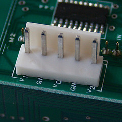
Power: JST VH connector: http://www.jst.co.uk/productSeries.php?pid=133

| Pin No. | Name | Function |
|---|---|---|
| 1 | V1 | Power supply for LED (red) |
| 2 | GND1 | Ground for IC |
| 3 | VDD | Power supply for IC |
| 4 | GND2 | Ground for LED |
| 5 | V2 | Power supply for LED (yellow-green) |
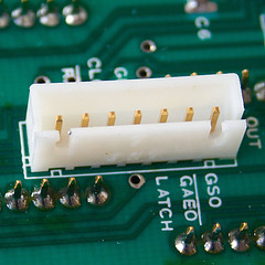
Data: JST XH connector: http://www.jst.co.uk/productSeries.php?pid=136

| Pin No. | Name | Function |
|---|---|---|
| 1 | GSI | Serial data yellow-green |
| 2 | /GAEO | Output enable for yellow-green |
| 3 | LATCH | Latch contents of shift register |
| 4 | GND1 | Ground of IC |
| 5 | CLOCK | Clock Signal for data (read on L->H) |
| 6 | /RAEO | Output enable for red |
| 7 | RSI | Serial data red |