Latest revision as of 11:49, 5 February 2019
Control System
General Description
The Barbot control system is based on an Arduino Mega 2560 and a Raspberry Pi. Power is from a PC ATX PSU.
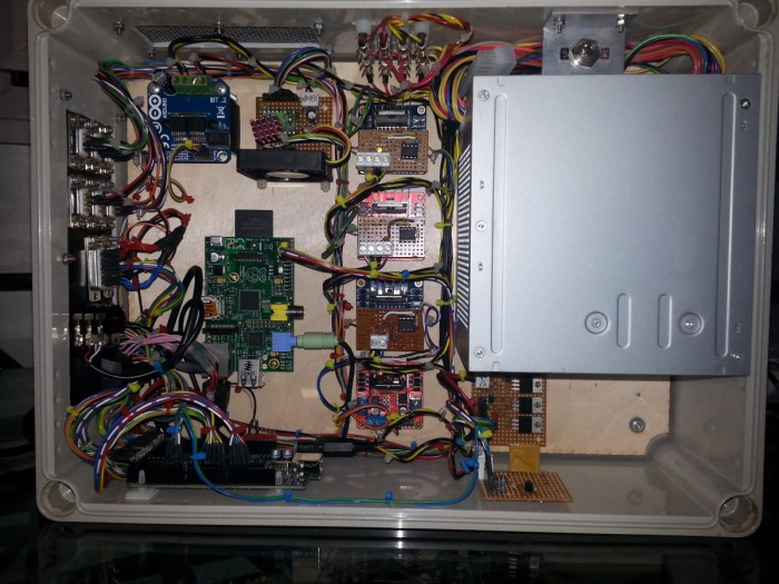
 Control box - internal layout
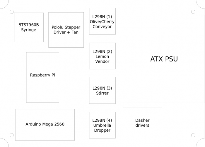
Control box layout
 Control box - internal layout
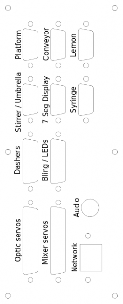
Connector panel
 Control panel with labels
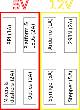
Fuses
 Control box - fuse layout
Platform (9 way 'D' skt)
| Pin no |
Signal |
Wire colour |
Pololu / Arduino
|
| 1 |
+5V supply |
Orange |
PSU +5V
|
| 2 |
Stepper coil A |
Green |
Pololu
|
| 3 |
Stepper coil A |
Purple |
Pololu
|
| 4 |
Stepper coil B |
Yellow |
Pololu
|
| 5 |
Stepper coil B |
Blue |
Pololu
|
| 6 |
Serial TX to platform |
White/black |
14 (TX3)
|
| 8 |
"Glass present" signal |
Grey |
15 (RX3)
|
| 9 |
Ground |
Black |
PSU 0V
|
Cherry / olive conveyor (9 way 'D' skt)
| Pin no |
Signal |
Wire colour |
L298N (1)
|
| 2 |
Stepper coil A |
Green |
OUT2
|
| 3 |
Stepper coil A |
Purple |
OUT1
|
| 4 |
Stepper coil B |
Yellow |
OUT4
|
| 5 |
Stepper coil B |
Blue |
OUT3
|
| 7 |
IR sensor |
Orange |
|
| 8 |
IR LED |
Grey |
|
| 9 |
Ground |
Black |
|
Lemon vendor (9 way 'D' skt)
| Pin no |
Signal |
Wire colour |
L298N (2)
|
| 2 |
Motor +ve |
Green |
OUT1
|
| 3 |
Motor -ve |
Purple |
OUT2
|
| 8 |
CAM switch |
White/black |
|
| 9 |
Ground |
Black |
PSU 0V
|
Stirrer and umbrella dropper (9 way 'D' skt)
| Pin no |
Signal |
Wire colour |
L298N (3/4)
|
| 1 |
Umbrella dropper |
Orange |
OUT1 (4)
|
| 6 |
Umbrella dropper |
Blue |
OUT2 (4)
|
| 2 |
Motor +ve (swizzler) |
Orange |
OUT1 (3)
|
| 3 |
Motor -ve (swizzler) |
Black |
OUT2 (3)
|
| 4 |
Motor -ve (up/down) |
Purple |
OUT3 (3)
|
| 5 |
Motor +ve (up/down) |
White/black |
OUT4 (3)
|
7 segment "days accident free" display (9 way 'D' skt)
| Pin no |
Signal |
Wire color |
Arduino
|
| 6 |
Reset |
Purple |
28
|
| 7 |
Clock |
White/blue |
29
|
| 9 |
Ground |
Black |
PSU 0V
|
Big Syringe (9 way 'D' skt)
| Pin no |
Signal |
Wire color |
BTS7960B
|
| 2 |
Motor +ve |
Red/brown |
OUT1
|
| 3 |
Motor -ve |
Black |
OUT2
|
Optic servos (25 way 'D' skt)
| Pin no |
Signal |
Wire colour |
Arduino / PSU
|
| 2 |
Ground |
Black |
PSU 0V
|
| 15 |
+5V supply |
Pink |
PSU +5V
|
| 3 |
Servo 0 |
Yellow |
40
|
| 16 |
Ground |
Black |
PSU 0V
|
| 4 |
+5V supply |
Pink |
PSU +5V
|
| 17 |
Servo 1 |
Green |
42
|
| 5 |
Ground |
Black |
PSU 0V
|
| 18 |
+5V supply |
Pink |
PSU +5V
|
| 6 |
Servo 2 |
Blue |
44
|
| 19 |
Ground |
Black |
PSU 0V
|
| 7 |
+5V supply |
Pink |
PSU +5V
|
| 20 |
Servo 3 |
Grey |
46
|
| 8 |
Ground |
Black |
PSU 0V
|
| 21 |
+5V supply |
Pink |
PSU +5V
|
| 9 |
Servo 4 |
Purple |
48
|
| 22 |
Ground |
Black |
PSU 0V
|
| 10 |
+5V supply |
Pink |
PSU +5V
|
| 23 |
Servo 5 |
Orange |
50
|
| 25 |
Spare / unused |
White/black |
52
|
| 13 |
Ground |
Black |
PSU 0V
|
Mixer servos (25 way 'D' skt)
| Pin no |
Signal |
Wire colour |
Arduino / PSU
|
| 2 |
Ground |
Black |
PSU 0V
|
| 15 |
+5V supply |
Pink |
PSU +5V
|
| 3 |
Servo 0 |
Yellow |
41
|
| 16 |
Ground |
Black |
PSU 0V
|
| 4 |
+5V supply |
Pink |
PSU +5V
|
| 17 |
Servo 1 |
Green |
43
|
| 5 |
Ground |
Black |
PSU 0V
|
| 18 |
+5V supply |
Pink |
PSU +5V
|
| 6 |
Servo 2 |
Blue |
45
|
| 19 |
Ground |
Black |
PSU 0V
|
| 7 |
+5V supply |
Pink |
PSU +5V
|
| 20 |
Servo 3 |
Grey |
47
|
| 8 |
Ground |
Black |
PSU 0V
|
| 21 |
+5V supply |
Pink |
PSU +5V
|
| 9 |
Servo 4 |
Purple |
49
|
| 22 |
Ground |
Black |
PSU 0V
|
| 10 |
+5V supply |
Pink |
PSU +5V
|
| 23 |
Servo 5 |
Orange |
51
|
| 24 |
Zero limit switch |
White/black |
37
|
| 12 |
Ground |
Black |
PSU 0V
|
| 25 |
Emergency stop switch |
White/black |
53
|
| 13 |
Ground |
Black |
PSU 0V
|
Dashers (15 way 'D' skt)
| Pin no |
Signal |
Wire colour |
Arduino
|
| 1 |
Motor common +ve |
Red/brown |
PSU +5V
|
| 2 |
Motor 0 -ve |
Yellow |
Dasher driver 0
|
| 3 |
Motor 1 -ve |
Green |
Dasher driver 1
|
| 4 |
Motor 2 -ve |
Blue |
Dasher driver 2
|
| 5 |
Cam switch 0 |
Purple |
22
|
| 6 |
Cam switch 1 |
Grey |
24
|
| 7 |
Cam switch 2 |
White/black |
26
|
| 8 |
Cam switch common ground |
Black |
PSU 0V
|
LEDs / bling (15 way 'D' skt)
| Pin no |
Signal |
Wire colour |
Arduino / PSU
|
| 1 |
+5V supply (Dashers) |
Red |
PSU +5V
|
| 9 |
+5V supply |
Red |
PSU +5V
|
| 2 |
+5V supply |
Red |
PSU +5V
|
| 10 |
+5V supply |
Red |
PSU +5V
|
| 3 |
Neopixel 0 (Dashers 24+24+24 LEDs) |
Yellow |
7
|
| 11 |
Neopixel 1 (Optics 6 LEDs) |
White/purple |
8
|
| 4 |
Neopixel 2 |
Purple |
9
|
| 12 |
Neopixel 3 |
Blue |
10
|
| 5 |
Neopixel 4 |
Green |
11
|
| 13 |
Neopixel 5 |
Red/blue |
12
|
| 14 |
Ground |
Blue |
PSU 0V
|
| 7 |
Ground (Dashers) |
Blue |
PSU 0V
|
| 15 |
Ground |
Blue |
PSU 0V
|
| 8 |
Ground |
Blue |
PSU 0V
|
Arduino Mega 2560 Connections
| Signal |
Arduino pin |
pinMode |
Signal type |
Wire colour
|
| Optic 0 |
40 |
OUTPUT |
servo |
Yellow
|
| Optic 1 |
42 |
OUTPUT |
servo |
Green
|
| Optic 2 |
44 |
OUTPUT |
servo |
Blue
|
| Optic 3 |
46 |
OUTPUT |
servo |
Grey
|
| Optic 4 |
48 |
OUTPUT |
servo |
Purple
|
| Optic 5 |
50 |
OUTPUT |
servo |
Orange
|
| Mixer 0 |
41 |
OUTPUT |
servo |
Yellow
|
| Mixer 1 |
43 |
OUTPUT |
servo |
Green
|
| Mixer 2 |
45 |
OUTPUT |
servo |
Blue
|
| Mixer 3 |
47 |
OUTPUT |
servo |
Grey
|
| Mixer 4 |
49 |
OUTPUT |
servo |
Purple
|
| Mixer 5 |
51 |
OUTPUT |
servo |
Orange
|
| Dasher 0 cam switch |
22 |
INPUT_PULLUP |
switch to ground |
Purple
|
| Dasher 0 driver |
23 |
OUTPUT |
LOW = motor off, HIGH = motor on |
Green
|
| Dasher 1 cam switch |
24 |
INPUT_PULLUP |
switch to ground |
Grey
|
| Dasher 1 driver |
25 |
OUTPUT |
LOW = motor off, HIGH = motor on |
Purple
|
| Dasher 2 cam switch |
26 |
INPUT_PULLUP |
switch to ground |
White/black
|
| Dasher 2 driver |
27 |
OUTPUT |
LOW = motor off, HIGH = motor on |
White/purple
|
| Cherry/olive conveyor start/stop |
38 |
OUTPUT |
Normally HIGH, pulse LOW for 10 msec to start, hold LOW to stop |
Yellow
|
| Cherry/olive conveyor end sensor |
39 |
INPUT_PULLUP |
LOW = sensor clear, HIGH = item at end of conveyor |
Orange
|
| Lemon vendor start |
34 |
OUTPUT |
Normally HIGH, pulse LOW for 10 msec to start |
Purple
|
| Stirrer start |
36 |
OUTPUT |
Normally HIGH, pulse LOW for 10 msec to start |
Blue
|
| Umbrella dropper |
32 |
OUTPUT |
Normally LOW, pulse HIGH for 500 msec |
Orange
|
| Big Syringe BTS7960B |
5 |
OUTPUT |
PWM |
Yellow
|
| Big Syringe BTS7960B |
6 |
OUTPUT |
PWM |
Purple
|
| Platform "glass present" |
15 (RX3) |
INPUT_PULLUP |
LOW = no glass, HIGH = glass present |
Grey
|
| Platform illumination control |
14 (TX3) |
OUTPUT |
serial (TX to platform only) |
White/black
|
| Pololu stepper driver |
2 |
OUTPUT |
Step |
Green/yellow
|
| Pololu stepper driver |
3 |
OUTPUT |
Direction |
Yellow
|
| Pololu stepper driver |
4 |
OUTPUT |
Enable |
White/black
|
| Optics 'D' type pin 25 (spare) |
52 |
INPUT_PULLUP |
Spare / unused |
White/black
|
| Zero limit switch |
37 |
INPUT_PULLUP |
LOW = at zero, HIGH = not at zero |
White/blue
|
| Emergency stop |
53 |
INPUT_PULLUP |
LOW = not pressed, HIGH = pressed |
White/black
|
| Neopixel 0 (Dashers) |
7 |
OUTPUT |
Neopixel serial (72 LEDs) |
Yellow
|
| Neopixel 1 (Optics) |
8 |
OUTPUT |
Neopixel serial (6 LEDs) |
White/purple
|
| Neopixel 2 |
9 |
OUTPUT |
Neopixel serial |
Purple
|
| Neopixel 3 |
10 |
OUTPUT |
Neopixel serial |
Blue
|
| Neopixel 4 |
11 |
OUTPUT |
Neopixel serial |
Green
|
| Neopixel 5 |
12 |
OUTPUT |
Neopixel serial |
Red/blue
|
| Serial to RPi (via level shifter) |
16 (TX2) |
OUTPUT |
serial TX |
Green
|
| Serial from RPi (via level shifter) |
17 (RX2) |
INPUT_PULLUP |
serial RX |
Blue
|
| 7 segment display - Reset |
28 |
OUTPUT |
Normally LOW, pulse HIGH to reset display to zero |
Purple
|
| 7 segment display - Clock |
29 |
OUTPUT |
Normally LOW, pulse HIGH to advance display |
White/blue
|
Raspberry Pi Connections
| Signal |
RPi pin |
Wire colour
|
| +3V3 |
1 |
Yellow
|
| +5V |
2 |
Red
|
| Ground |
6 |
Black
|
| TXD (to Arduino via level shifter) |
8 |
Purple
|
| RXD (from Arduino via level shifter) |
10 |
White/purple
|


