User:Danspencer101/Sandbox: Difference between revisions
mNo edit summary |
mNo edit summary |
||
| Line 16: | Line 16: | ||
== Build Instructions == | == Build Instructions == | ||
=Robot/Round Badge= | =Robot/Round Badge= | ||
<gallery | <gallery> | ||
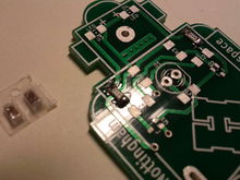
File:Robot_(2).jpg| | File:Robot_(2).jpg| | ||
Spread out the parts: PCB, LED, Battery Holder, Battery, Pin, Clasp| | Spread out the parts: PCB, LED, Battery Holder, Battery, Pin, Clasp| | ||
Revision as of 22:08, 13 June 2019
| Robot Badge | |
|---|---|
 | |
| Primary Contact | Chunky |
| Created | 24/05/2013 |
| Completed | 27/05/2013 |
| Status | Complete |
| Type | Workshop Activity |
Overview
These are notes and files relating to the 'Learn To Solder' Robot Badge. This badge kit has been produced to use at events as a simple soldering exercise and promote the hackspace. This badge was based upon a simple flashing LED badge that was seen at UK Maker Faire 2011 in Newcastle. This robot shaped badge was designed by Matt Little based on an idea by Rob Keating from PCB manufacturers, Beta Layout. Beta Layout produced a number of batches of these PCBs for Nottingham Hackspace.
Build Instructions
Robot/Round Badge
SMD Robot Badge
Parts List - Simple
The simple version of the badge is just an LED wired derectly with a battery. A colour changing LED is used to make it a bit more interesting.
| Part | Details | Supplier |
| 3V Battery | CR2032 | eBay 1 Cost: £10 for 100
eBay 2 Cost: £10 for 100 |
| Battery clip | To hold above | Rapid: 18-3585 Cost: £0.312 100+
Farnell: 908654 Cost: £0.442 100+ Digikey UK: BK-888-ND Cost: £0.1674 100+ |
| LED | 5mm colour chaging | Rapid: 55-1906 £0.4326 100+
eBay 1: Cost: £6.99 for 30 eBay 2: Cost: £3.50 for 30 |
| Pin | 13mm panel pin | Stones hardware £0.56 for box (100pcs)
eBay 1 £1.60 for box |
| Badge Clip | To fit above pin | eBay 1: Cost: £4.99 for 100
eBay 2: Cost: £3 for 100 |
Parts List - SMD
The SMD version of the badge was designed for more advanced users so they can learn to do surface mount soldering or use an SMD oven. The circuit is a Flip Flop Two Transistor Flasher. The schematic diagram is here: ADD a PHOTO/PDF HERE
| Part | Reference | Details | Supplier |
| Capacitor | C1, C2 | Control flash rate. 10uf used. Size: 1206. | RS: 740-7546 |
| Resistor | R2, R3 | Control Flash Rate. 100k used. Size: 1206 | Rapid: 72-1437 |
| Resistor | R1, R4 | Limit LED current. 0 ohm with 3V battery. Size: 1206 | Rapid: 72-1207 |
| Transistor | Q1, Q2 | NPN type. S0323. BC817W used. | Farnell: 2114873 |
| LED | D3, D4 | Red or Green. Not enough voltage for Blue/White. Size: 1206 | Green. RS: 466 3908 |
PCB Files
The PCB was designed using KiCAD - an open source PCB design package.


