Raspberry Pi Arduino Buffer: Difference between revisions
No edit summary |
No edit summary |
||
| Line 47: | Line 47: | ||
The Pi UART on the GPIO on my distro is used as a console but this can easily be disabled (see http://elinux.org/RPi_Serial_Connection) | The Pi UART on the GPIO on my distro is used as a console but this can easily be disabled (see http://elinux.org/RPi_Serial_Connection) | ||
The Arduino is happy to receive 3.3v logic on its RX pin | The Arduino is happy to receive 3.3v logic on its RX pin but TX to the Pi will require a step-down from 5v to 3.3. I could use a logic level converter like this one at SparkFun http://www.sparkfun.com/products/8745 - however, I've found that a simple voltage divider works for most jobs. You can go from 5v to 3.3v with 2 resistors that give a 66%/33% split or with 3 identical resistors. | ||
[[Link title]] | [[Link title]] | ||
Revision as of 23:01, 13 July 2012
An Arduino interface to save the precious Raspberry Pi from the outside world.
The presence of GPIO on the Raspberry Pi opens up the world of physical computing to a new audience of hobbyist programmers and this can only be a good thing. I ran a few simple GPIO tests with the pi and I have to say I was truly scared that I would damage it! The GPIO is rather "raw" and the pins have no protection. Just fitting a plain cable to the 26 pin header with nothing attached, I am quite able to cause hangs and crashes! This is known behaviour: from http://elinux.org/RPi_Serial_Connection#Unwanted_serial_garbage_input ...
Note that on older software by accident the internal pullups of the RxD GPIO pins were not enabled, this could lead to lots of serial garbage being picked up if the GPIO pin was touched, or even if a finger was nearby. In extreme case this could lead to kernel warnings and other problems.
I get this with 2012-06-18-wheezy-beta but I guess there's a fix and things will improve in good time.
All things considered, it seems to me that I need to build a protection board for the Pi...
And then I'd have to rewrite all my perfectly functional Arduino sketches to run on the pi...
And I'd have to adapt all my sensors to work with 3.3v logic...
And I'd need to find an analogue to digital converter for my analogue inputs...
And then I'd no doubt run out of Digital pins...
And then I'd want to use digital inputs with interrupts...
So, why not just use an Arduino and talk to it over the Pi UART? An ATMega328P is about £3.50 and I don't care too much if I blow one up. If I blow up my Pi it will be months before I can get my hands on another!
OK, so I'm convinced: I'll build an Arduino clone that plugs into the Raspberry Pi.
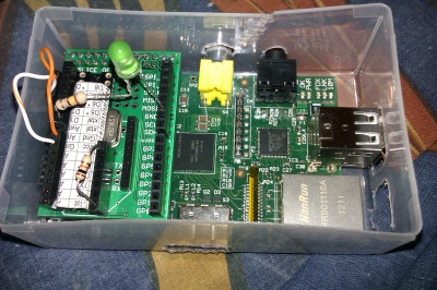
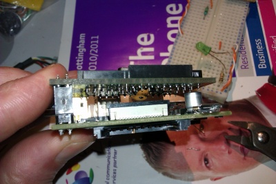
This first one uses a Ciseco Slice of Pi -- I was feeling lazy and didn't want to spend too much time looking for bits and besides, there were loads of them in the vending machine at the Hackspace for just £4 so it's a no-brainer!
The proto board is just big enough for the 28 pin DIP - I desoldered a couple of 16 pin DIP sockets from an old prototype board found at the hackspace. This leaves me with 4 spare socket pins at one end which I'll no doubt use in the future.
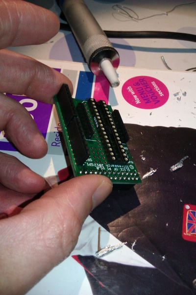
I had to break up one of my breadboard minimal Arduino clones for parts - no big problem, they're easy enough to make.
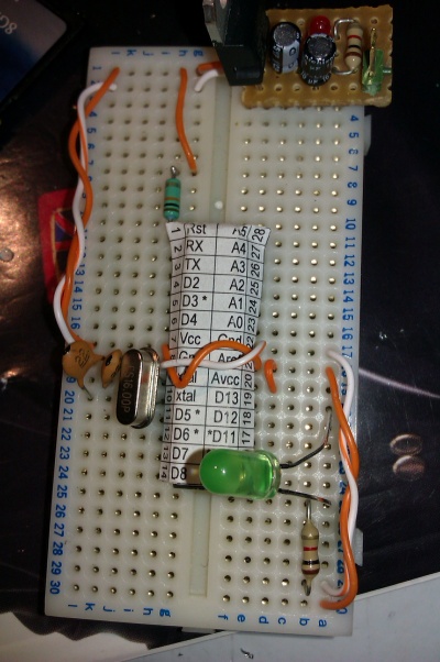
The Arduino is extremely minimal right now! We have the 16MHz crystal with its two 22pF caps, the ground pins connected, the VCC, AREF, and AVREF all connected. I still haven't put a pullup resistor on the reset pin so that is just plugged in on top.
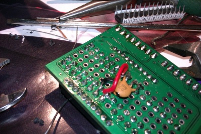
I've broken out most of the pins to strips of female headers. The crystal takes up some room so I've left D5-D8 for now.
Programming the 328 is straightforward enough with FTDI-board my FTDI development board I got some time ago - any FTDI or Prolific PL2303 USB-UART will do. Initially I'll be disconnecting from the Pi for programming but it makes sense to eventually program the 328 directly from the Pi UART using avrdude.
The Pi UART on the GPIO on my distro is used as a console but this can easily be disabled (see http://elinux.org/RPi_Serial_Connection)
The Arduino is happy to receive 3.3v logic on its RX pin but TX to the Pi will require a step-down from 5v to 3.3. I could use a logic level converter like this one at SparkFun http://www.sparkfun.com/products/8745 - however, I've found that a simple voltage divider works for most jobs. You can go from 5v to 3.3v with 2 resistors that give a 66%/33% split or with 3 identical resistors.
Link title Tested distribution: 2012-06-18-wheezy-beta (http://downloads.raspberrypi.org/images/debian/7/2012-06-18-wheezy-beta.zip)
Soon to test raspbian