Raspberry Pi Arduino Buffer
An Arduino interface to save the precious Raspberry Pi from the outside world.
The presence of GPIO on the Raspberry Pi opens up the world of physical computing to a new audience of hobbyist programmers and this can only be a good thing. I ran a few simple GPIO tests using Perl to drive the memory mapped /dev ports just to light LEDs and read pushbuttons but I have to say I was truly scared that I would damage my precious Pi! The GPIO is rather "raw" and the pins have no protection. Just fitting a plain cable to the 26 pin header with nothing attached, I am quite able to cause hangs and crashes! This is known behaviour: from http://elinux.org/RPi_Serial_Connection#Unwanted_serial_garbage_input ...
Note that on older software by accident the internal pullups of the RxD GPIO pins were not enabled, this could lead to lots of serial garbage being picked up if the GPIO pin was touched, or even if a finger was nearby. In extreme case this could lead to kernel warnings and other problems.
I get this with 2012-06-18-wheezy-beta but I guess there's a fix coming in the next kernel and things will improve in good time.
All things considered, it seems to me that I need to build a protection board for the Pi...
And then I'd have to rewrite all my perfectly functional Arduino sketches to run on the pi...
And I'd have to adapt all my sensors to work with 3.3v logic...
And I'd need to find an analogue to digital converter for my analogue inputs...
And then I'd no doubt run out of Digital pins...
And then I'd want to use digital inputs with interrupts...
So, why not just use an Arduino and talk to it over the Pi UART? An ATMega328P is about £3.50 and I don't care too much if I blow one up. If I blow up my Pi it will be months before I can get my hands on another!
OK, so I'm convinced: I'll build an Arduino clone that plugs into the Raspberry Pi.
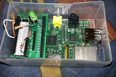
This first one uses a Ciseco Slice of Pi -- I was feeling lazy and didn't want to spend too much time looking for bits and besides, there were loads of them in the vending machine at the Hackspace for just £4 so it's a no-brainer!
The proto board is just big enough for the 28 pin DIP - I desoldered a couple of 16 pin DIP sockets from an old prototype board found at the hackspace. This leaves me with 4 spare socket pins at one end which I'll no doubt use in the future.
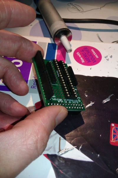
I had to break up one of my breadboard minimal Arduino clones for parts - no big problem, they're easy enough to make. This one is just an ATMega328P, a crystal, two capacitors, and a 10k pullup on the reset pin. I won't be needing the little 5v voltage regulator board as I'll be taking power from the handy 5v on one of the Pi GPIO pins.
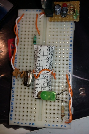
This minimal Arduino can be crammed onto the Slice of Pi protoboard. Here on the underside we can see: -
- the two 22pF caps that go from the 16MHz crystal pins to ground
- the red wire connecting up VCC, AREF, and AVREF and breaking out to a headers
- the black wire connecting the GND pins left and right and breaking out to headers
- most of the digital and analogue IO pins have been connected to the breakout headers. The crystal takes up some room on the top side so I've left D5-D8 for now.
- I still haven't put a pullup resistor on the reset pin so that is just plugged in between pin 1 and VCC on top.
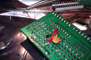
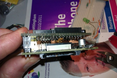
The clearance is OK. It doesn't help that I soldered the 26 pin GPIO connector slightly wonky! I'm going to use a little insulating hat on the can at the loose end to support the slice.
Programming the 328 is straightforward enough with FTDI-board my FTDI development board I got some time ago - any FTDI or Prolific PL2303 USB-UART will do. Initially I'll be disconnecting from the Pi for programming but it makes sense to eventually program the 328 directly from the Pi UART using avrdude.
The Pi UART on the GPIO (see http://elinux.org/RPi_Serial_Connection) on my 2012-06-18-wheezy-beta distro is on /dev/ttyAM0 and is used as a boot console and getty but this can easily be disabled in /boot/cmdline.txt and /etc/innitab.
The Arduino is happy to receive 3.3v logic on its RX pin but TX to the Pi will require a step-down from 5v to 3.3. I could use a logic level converter like this one at SparkFun http://www.sparkfun.com/products/8745 - however, I've found that a simple voltage divider works for most jobs. You can go from 5v to 3.3v with 2 resistors that give a 66%/33% split (3.3v is 66% of 5v) or with 3 identical resistors.
#include <stdio.h>
#include <string.h>
#include <unistd.h>
#include <fcntl.h>
#include <errno.h>
#include <termios.h>

#include <sys/types.h>
#include <sys/stat.h>

int main(int argc, char ** argv) {
  int fd;
  fd = open("/dev/ttyAMA0", O_WRONLY | O_NOCTTY | O_NDELAY | O_NONBLOCK);
  if (fd == -1) {
    perror("open_port: Unable to open /dev/ttyAMA0 - ");
    return(-1);
  }
  struct termios options;
  tcgetattr(fd, &options);
  cfsetispeed(&options, B9600);
  cfsetospeed(&options, B9600);
  options.c_cflag = B9600 | CS8 | CLOCAL | CREAD;
  options.c_iflag = IGNPAR | ICRNL;
  options.c_oflag = 0;
  tcflush(fd, TCIFLUSH);
  tcsetattr(fd, TCSANOW, &options);

  int res = fprintf(fd, "Hello there!\n");
  if (!res) {
    perror("write error");
    return -1;
  }
  close(fd);
  return 0;
}
Test code for arduino end
Using some Cheesoid code...
/*******************************************************************/
/*                          CHEESOID MCU1                          */
/*******************************************************************/

// I/O Pin definitions...
// The mode switch is on a digital input...
const int PIN_MODESW = 4;
// Two LEDs are used for eyes on two digital pins...
const int PIN_EYE1 = 7;
const int PIN_EYE2 = 8;
// Built-in LED on pin 13 used for watchdog status...
const int PIN_WDLED = 13;
// Motor enable/speed PWM outputs...
const int PIN_M1SPD = 9;
const int PIN_M2SPD = 10;
// Motor control logic digital outputs...
const int PIN_M1C1 = 14;
const int PIN_M1C2 = 15;
const int PIN_M2C1 = 16;
const int PIN_M2C2 = 17;
// Bumper inputs...
const int PIN_BMP1 = 18;
const int PIN_BMP2 = 19;
// Soft serial to MCU2...
const int PIN_MCU2TX = 11;


// Last watchdog time tracking...
unsigned long wdoglast = 0;
// main loop has 10ms sleeps...
const int naptime = 10;
// the eyes flash every 60 loops = 600ms...
int eyefreq = 60;
// info is sent out on the serial port every 90 loops = 900ms...
int reportfreq = 90;
// a simple loop counter is used to decide what to do...
unsigned int loopcounter = 0;
// mode switch state...
int mode = 0;

// System counters...
// Max number of bytes read in one go...
#define CTR_MAXREAD 0
// number of buffer overflows avoided...
#define CTR_OVERFLOW 1
// Number of bytes received...
#define CTR_BYTES 2
// Number of unknown message commands...
#define CTR_UNKMSG 3
// Number of unknown message commands...
#define CTR_WDOGTO 4
static int counters[4];
// watchdog timout in millis...
#define WDOG_TIMEOUT (long)7000
// size of our incoming message buffer...
#define MAXMSG 50

void setup() {
  Serial.begin(9600);
  pinMode(PIN_MODESW, INPUT);
  pinMode(PIN_EYE2, OUTPUT);
  pinMode(PIN_EYE1, OUTPUT);
  pinMode(PIN_WDLED, OUTPUT);
  //
  pinMode(PIN_M1SPD, OUTPUT);
  pinMode(PIN_M2SPD, OUTPUT);
  pinMode(PIN_M1C1, OUTPUT);
  pinMode(PIN_M1C2, OUTPUT);
  pinMode(PIN_M2C1, OUTPUT);
  pinMode(PIN_M2C2, OUTPUT);
  // TODO soft serial link to MCU2
  pinMode(PIN_MCU2TX, OUTPUT);
  //
  pinMode(PIN_BMP1, INPUT);
  pinMode(PIN_BMP2, INPUT);

  // announce startup...
  flasheyes(200);
  Serial.println("\n=== CHEESOID ===");
  // TODO: piezo buzzer to play a tune
  mode = digitalRead(PIN_MODESW);
}

void flasheyes(int zeds) {
  for(int i=0;i<6;i++){
    int onoff = i % 2;
    digitalWrite(PIN_EYE2, onoff);
    digitalWrite(PIN_EYE1, onoff);
    delay(zeds);
  }
}

void loop() {
  static int act;
  do_switch();
  do_eyes();
  act = do_report();
  act += do_serialinput();
  if(!act)
    delay(naptime);
  loopcounter++;
}

void do_switch() {
  // button debounce: state must remain stable for N samples.
  // This is just a lightweight debouncer
  // used if we want to avoid the more general purpose
  // but heavyweight Bounce library.

  const int debouncesamples = 5;
  static int lastsample = 0;
  static int steadycount = 0;
  static int debounced = 0;
  // if the value is steady for
  int sample = digitalRead(PIN_MODESW);
  // a change of value - restart the steady count...
  if(sample != lastsample){
    lastsample = sample;
    steadycount = 0;
    return;
  }
  steadycount++;
  if(steadycount < debouncesamples)
    return;
  steadycount = debouncesamples;
  debounced = sample;
  // set the actual mode switch value
  mode = debounced;
}

void do_eyes() {
  static int eyestate = 0;
  if(loopcounter % eyefreq != 0)
    return;
  eyestate = !eyestate;
  digitalWrite(PIN_EYE2, eyestate);
  digitalWrite(PIN_EYE1, !eyestate);
}

int do_report() {
  if(loopcounter % reportfreq != 0)
    return 0;
  Serial.print("CHEESOID: mode = ");
  Serial.print(mode);
  //~ Serial.print(" | eye = ");
  //~ Serial.print(onoff);
  Serial.print(" | loop = ");
  Serial.println(loopcounter);

  // also timeout the watchdog if set...
  // this activity is limited by the reportfreq
  if(wdoglast != 0){
    long now = millis();
    if(now - wdoglast > WDOG_TIMEOUT){
      digitalWrite(PIN_WDLED, LOW);
      counters[CTR_WDOGTO]++;
      wdoglast = 0;
    }
  }
  return 100;
}

int do_serialinput() {
  // can we avoid buffer overflows when using the
  // standard serial library at a 10ms read rate at 9600 baud?
  // Well, 9600 8-n-1 is 960 bytes per sec or 9.6 per 10ms
  // The standard serial receive buffer holds 128 bytes so we're fine
  // already nulled by compiler - we leave the final char alone!
  static char msgbuf[MAXMSG+2];
  static int len = 0;
  // any data waiting?
  int ba = Serial.available();
  if(!ba)
    return 0;
  if(ba > counters[CTR_MAXREAD])
    counters[CTR_MAXREAD] = ba;
  for(int i = 0; i < ba; i++){
    int c = Serial.read();
    Serial.print("GOT:");
    Serial.println(c, DEC);
    // upon LF, process message...
    if(c == 0x0A){
      // NB: ignore incoming char - now looking at the buffer...
      c = msgbuf[0];
      if(c == 'E'){
        flasheyes(50);
        Serial.println("I OBEY: FLASH EYES!");
        len = 0; // reset message
        continue; // ignore rest of message!
      }
      // watchdog kick - proof that PC is alive
      if(c == 'W'){
        // LED on for a while (needs timeout)
        // lastkick var
        Serial.println("Watchdog!");
        digitalWrite(PIN_WDLED, HIGH);
        wdoglast = millis();
        len = 0; // reset message
        continue; // ignore rest of message!
      }
      // Drive command...
      if(c == 'D'){
        DriveInterpret(msgbuf, len);
        len = 0; // reset message
        continue;
      }
      // Test commands...
      if(c == 'T'){
        int testmode = msgbuf[1];
        if(testmode == 'D') {
            TestMotors();
            len = 0;
            continue;
        }
        len = 0; // reset message
        continue;
      }
      counters[CTR_UNKMSG]++;
      continue;
    }
    // check for and avoid overflow...
    if(len > MAXMSG){
      counters[CTR_OVERFLOW]++;
      len = 0; // reset message
      continue;
    }
    // add msg to end of buffer and carry on...
    msgbuf[len] = c;
    len++;
    // null terminate for debugging - OK to do if buffer len is MAXMSG+2!
    msgbuf[len] = '\0';
  }
  return ba;
}

/*******************************************************************/
/*                  Motor drive control messages                   */
/*******************************************************************/
//
//~ D[L-dir][L-speed][R-dir][R-speed]
//
//~ direction = 1 char, 'F' = forwards, 'B' = backwards, 'X' = hold
//~ speed = 3 ASCII decimal digits in range 000 to 255 left zero padded
//
// Each message is 9 chars long.
//
//~ Examples: -
//~ DF255F255 = full speed ahead
//~ DF127F127 = half speed ahead
//~ DF000F000 = freewheel?
//~ DX000X000 = hold stop
//~ DB255F255 = fast rotate left
//~ DF255B255 = fast rotate right
//~ DX000F255 = fast pivot left
//~ The PWM will continue unless stopped so we should have a timeout on MCU1
/*******************************************************************/
void DriveInterpret(const char* msg, int len)
{
  int pwm1, pwm2, motor1_c1, motor1_c2, motor2_c1, motor2_c2;
  // Validate input
  if(msg == 0 || len < 9 || msg[0] != 'D')
      return;
  pwm1 = ((msg[2]-'0')*100) + ((msg[3]-'0')*10) + (msg[4]-'0');
  pwm2 = ((msg[6]-'0')*100) + ((msg[7]-'0')*10) + (msg[8]-'0');
  // the motor directions are rather arbitrary as they
  // can be easily wired as necessary
  if(msg[1] == 'F'){
    motor1_c1 = HIGH;
    motor1_c2 = LOW;
  } else if(msg[1] == 'B'){
    motor1_c1 = LOW;
    motor1_c2 = HIGH;
  } else { // default to hold
    motor1_c1 = LOW;
    motor1_c2 = LOW;
  }
  if(msg[5] == 'F'){
    motor1_c1 = HIGH;
    motor1_c2 = LOW;
  } else if(msg[5] == 'B'){
    motor1_c1 = LOW;
    motor1_c2 = HIGH;
  } else { // default to hold
    motor1_c1 = LOW;
    motor1_c2 = LOW;
  }
  DriveMotors(motor1_c1, motor1_c2, pwm1, motor2_c1, motor2_c2, pwm2);
}

void DriveMotors(int motor1_c1, int motor1_c2, int pwm1,
    int motor2_c1, int motor2_c2, int pwm2)
{
    // TODO timeout and bumpers!
    digitalWrite(PIN_M1C1, motor1_c1);
    digitalWrite(PIN_M1C2, motor1_c2);
    analogWrite(PIN_M1SPD, pwm1);
    digitalWrite(PIN_M2C1, motor2_c1);
    digitalWrite(PIN_M2C2, motor2_c2);
    analogWrite(PIN_M2SPD, pwm2);
}

// Test motors forever!
void TestMotors()
{
#define INC_TESTS
#ifdef INC_TESTS

    char m[10];
    int len = 9;
    m[9] = '\0';
    m[0] = 'D';
    for(;;){
        DriveInterpret("DF255F255", len);
        delay(400);
        DriveInterpret("DF255X255", len);
        delay(400);
        DriveInterpret("DX255F255", len);
        delay(400);
        DriveInterpret("DF128F128", len);
        delay(400);
        DriveInterpret("DF255B255", len);
        delay(400);
        DriveInterpret("DB255F255", len);
        delay(400);
        DriveInterpret("DF000F000", len);
        delay(400);
        DriveInterpret("DF100F100", len);
        delay(400);
        DriveInterpret("DF150F150", len);
        delay(400);
        DriveInterpret("DF200F200", len);
        delay(400);
        DriveInterpret("DX000X000", len);
        delay(2000);
    }

#endif /* INC_TESTS */
}
Tested distribution: 2012-06-18-wheezy-beta (http://downloads.raspberrypi.org/images/debian/7/2012-06-18-wheezy-beta.zip)
Soon to test raspbian