Benchtop Mill: Difference between revisions
mNo edit summary |
No edit summary |
||
| (5 intermediate revisions by 3 users not shown) | |||
| Line 11: | Line 11: | ||
|defunctdate= | |defunctdate= | ||
}} | }} | ||
This is a Wabeco 11400 / F1210 precision milling machine which arrived as a result of the | This is a Wabeco 11400 / F1210 precision milling machine which arrived as a result of the [[New_Tools_May_2016/Pledge_Drive]]. | ||
The mill is currently located on a workbench against the back wall near the [[Metalworking Area]] and the fire doors. Wooden covers have been made to protect the bed, please ensure these are replaced after use. | The mill is currently located on a workbench against the back wall near the [[Metalworking Area]] and the fire doors. Wooden covers have been made to protect the bed, please ensure these are replaced after use. | ||
| Line 25: | Line 25: | ||
== Documentation == | == Documentation == | ||
https://www.manualslib.com/products/Wabeco-F1210-3879189.html | |||
PDF version: https://mdaprecision.com/wp-content/uploads/2015/05/Mills_with_dovetails_2014.pdf | |||
== Safety == | == Safety == | ||
Do not, ''ever'', use an ordinary Jacobs-type drill chuck to hold milling tools. Collet chucks are a much more secure and safe way of holding such tools (a drill-chuck is fine when the operating force is along the axis, but will loosen dangerously if sideways forces are applied). | Do not, ''ever'', use an ordinary Jacobs-type drill chuck to hold milling tools. Collet chucks are a much more secure and safe way of holding such tools (a drill-chuck is fine when the operating force is along the axis, but will loosen dangerously if sideways forces are applied). | ||
== Drawbars == | |||
Please follow the correct install procedure for the draw bars (TODO: dig up good docs / video of this process) | |||
Also not there are two different size bars for different collets, check the drawbar against the collect before installing. | |||
[[File:Benchtop Mill Drawbars.jpeg|600px]] | |||
[[File:Benchtop Mill Drawbars marking.jpeg|600px]] | |||
<br stlye="clear"> | |||
'''READ THIS BEFORE USE''' | |||
=== Fitting and removing the tools === | |||
[[File:Benchtop Mill Drawbar.png|600px|right]] | |||
The tool tightening and removing screw has a fine thread at the head, and a coarse thread on the shaft. Due to this construction, a special procedure must be followed when fitting and removing tools.<br> | |||
To make this easier to understand, the image shows a cut-away of the protective hood and the spindle housing. The cross-section shows the tool screw (2) and the Allen key (1). | |||
==== To change the tool, proceed as follows: ==== | |||
===== Tensioning tools with inner thread ===== | |||
# Screw the tool tightening screw (2) clockwise using the Allen key (1) into the main spindle up to the end of the thread. | |||
# When the tool tightening screw (2) is at the end of the thread, undo by 2 - 3 turns. | |||
# Now the tool (e.g. the collet chuck (5)) is inserted by hand from below into the ball of the tool spindle (3) and screwed anti-clockwise onto the tool tightening screw (2). The Allen key (1) is used to hold the tool tightening screw (2) in place. | |||
# When the tool has been hand-tightened, the holding bolt (4) is used to hold the tool spindle (3) and tighten the tool tightening screw (2) clockwise without great strength using the Allen key (1). | |||
===== Removing tools with an inner thread ===== | |||
# Hold the tool spindle (3) with the holding bolt (4). | |||
# Undo the tool tightening screw (2) using the Allen key (1) by turning anti-clockwise. To undo the tool tightening screw (2) turn the Allen key (1) forcefully until the cone comes undone. | |||
# Now unscrew the tool clockwise by hand from the tool tightening screw (2) and remove from below from the ball of the tool spindle (3). | |||
===== Tensioning tools with take-up(without inner thread) ===== | |||
# Undo the tool tightening screw (2) using the Allen key (1) far enough that the take-up is no longer up against that tool tightening screw (2). | |||
# Press the tool with a forceful push into the tool spindle (3). | |||
===== Removing tools with take-up(without inner thread) ===== | |||
# Insert the holding bolt (4) in the tool spindle (3) and hold with one hand. | |||
# Rotate the Allen key (1) clockwise, this releases the tool which will fall out of the tool spindle (3). In order to prevent damages, place something under the tool to catch it gently. | |||
[[Category:Tools_and_Equipment]] | [[Category:Tools_and_Equipment]] | ||
[[Category:Metalwork]] | [[Category:Metalwork]] | ||
Latest revision as of 13:34, 20 June 2023
| Benchtop Mill | |
|---|---|
 | |
| Manufacturer | Wabeco |
| Model | F1210 |
| Obtained | Pledge Drive (May 2016) |
| Location | Metalworking Area |
| Team | Metalworking |
| Induction Required | No |
| Tools: all pages • list • Power Tools • Broken tools {{}} | |
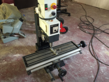
This is a Wabeco 11400 / F1210 precision milling machine which arrived as a result of the New_Tools_May_2016/Pledge_Drive.
The mill is currently located on a workbench against the back wall near the Metalworking Area and the fire doors. Wooden covers have been made to protect the bed, please ensure these are replaced after use.
Accessories
The Benchtop mill has the following accessories available:
- Milling vice
- Digital caliper-type XYZ readouts
- Dial indicator and mounting
In addition to these, there are tools and additional accessories available in the drawer immediately below the machine.
Documentation
https://www.manualslib.com/products/Wabeco-F1210-3879189.html
PDF version: https://mdaprecision.com/wp-content/uploads/2015/05/Mills_with_dovetails_2014.pdf
Safety
Do not, ever, use an ordinary Jacobs-type drill chuck to hold milling tools. Collet chucks are a much more secure and safe way of holding such tools (a drill-chuck is fine when the operating force is along the axis, but will loosen dangerously if sideways forces are applied).
Drawbars
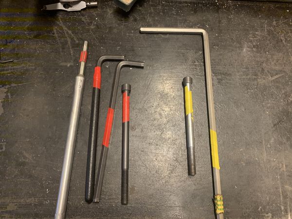
Please follow the correct install procedure for the draw bars (TODO: dig up good docs / video of this process)
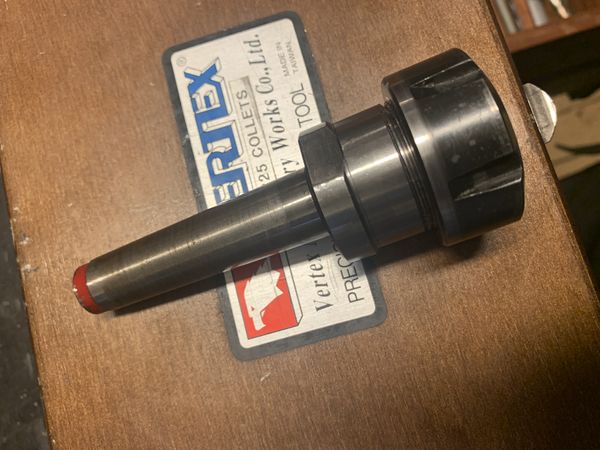
Also not there are two different size bars for different collets, check the drawbar against the collect before installing.


READ THIS BEFORE USE
Fitting and removing the tools

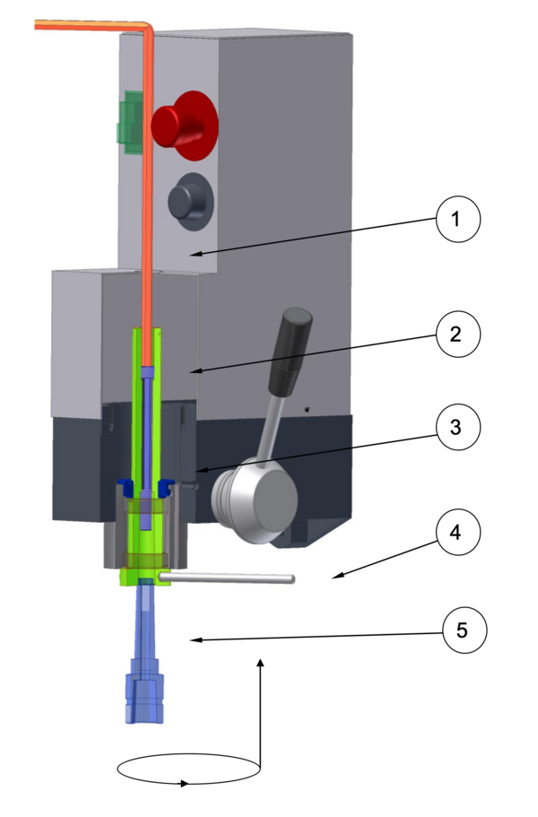
The tool tightening and removing screw has a fine thread at the head, and a coarse thread on the shaft. Due to this construction, a special procedure must be followed when fitting and removing tools.
To make this easier to understand, the image shows a cut-away of the protective hood and the spindle housing. The cross-section shows the tool screw (2) and the Allen key (1).
To change the tool, proceed as follows:
Tensioning tools with inner thread
- Screw the tool tightening screw (2) clockwise using the Allen key (1) into the main spindle up to the end of the thread.
- When the tool tightening screw (2) is at the end of the thread, undo by 2 - 3 turns.
- Now the tool (e.g. the collet chuck (5)) is inserted by hand from below into the ball of the tool spindle (3) and screwed anti-clockwise onto the tool tightening screw (2). The Allen key (1) is used to hold the tool tightening screw (2) in place.
- When the tool has been hand-tightened, the holding bolt (4) is used to hold the tool spindle (3) and tighten the tool tightening screw (2) clockwise without great strength using the Allen key (1).
Removing tools with an inner thread
- Hold the tool spindle (3) with the holding bolt (4).
- Undo the tool tightening screw (2) using the Allen key (1) by turning anti-clockwise. To undo the tool tightening screw (2) turn the Allen key (1) forcefully until the cone comes undone.
- Now unscrew the tool clockwise by hand from the tool tightening screw (2) and remove from below from the ball of the tool spindle (3).
Tensioning tools with take-up(without inner thread)
- Undo the tool tightening screw (2) using the Allen key (1) far enough that the take-up is no longer up against that tool tightening screw (2).
- Press the tool with a forceful push into the tool spindle (3).
Removing tools with take-up(without inner thread)
- Insert the holding bolt (4) in the tool spindle (3) and hold with one hand.
- Rotate the Allen key (1) clockwise, this releases the tool which will fall out of the tool spindle (3). In order to prevent damages, place something under the tool to catch it gently.