FTDI-board: Difference between revisions
No edit summary |
m Danspencer101 moved page Project:FTDI-board to FTDI-board over redirect |
||
| (7 intermediate revisions by 4 users not shown) | |||
| Line 1: | Line 1: | ||
{{Project|primary=[[User:Msemtd|Michael Erskine]]|created=04/06/2011|status=Complete}} | |||
Whilst working with the Xino, Paperduino, stripboarduino, breaduino, etc. I find that I need to keep swapping my microprocessor chips in and out of my Duemilanove to program them. Now, this isn't because I haven't tried programming them in-situ - I have and I have failed miserably! | Whilst working with the Xino, Paperduino, stripboarduino, breaduino, etc. I find that I need to keep swapping my microprocessor chips in and out of my Duemilanove to program them. Now, this isn't because I haven't tried programming them in-situ - I have and I have failed miserably! | ||
| Line 38: | Line 40: | ||
So we just need a single extra connection for the 6th pin - keeping it disconnected for now. | So we just need a single extra connection for the 6th pin - keeping it disconnected for now. | ||
14:52, 14 June 2011 (BST) Hooray! The Nanode programming connector now works! The problem was my reading of the pinouts of the FTDI cables which is seemingly different to the Nanode header. I can't imagine how everyone else's FTDI cable works. Never mind! | |||
Here's a blinky for the Nanode using D6 instead of D13... | |||
<syntaxhighlight lang="cpp">void setup() { | |||
pinMode(6, OUTPUT); | |||
} | |||
void loop() { | |||
digitalWrite(6, HIGH); | |||
delay(100); | |||
digitalWrite(6, LOW); | |||
delay(100); | |||
digitalWrite(6, HIGH); | |||
delay(100); | |||
digitalWrite(6, LOW); | |||
delay(100); | |||
digitalWrite(6, HIGH); | |||
delay(100); | |||
digitalWrite(6, LOW); | |||
delay(600); | |||
}</syntaxhighlight> | |||
[[Category:Projects]] | [[Category:Projects]] | ||
Latest revision as of 11:52, 5 February 2019
| FTDI-board | |
|---|---|
| Primary Contact | Michael Erskine |
| Created | 04/06/2011 |
| Status | Complete |
Whilst working with the Xino, Paperduino, stripboarduino, breaduino, etc. I find that I need to keep swapping my microprocessor chips in and out of my Duemilanove to program them. Now, this isn't because I haven't tried programming them in-situ - I have and I have failed miserably!
Now I have one of these bad boys: a UM232R development module: -
- http://www.ftdichip.com/Products/Modules/DevelopmentModules.htm#UM232R
- Datasheet: http://www.ftdichip.com/Support/Documents/DataSheets/Modules/DS_UM232R.pdf
Which is great, but I still haven't dedicated enough time to making it do all the Arduino programming tasks I require. So here I intend to detail my thoughts and document what I find out.
OK, most people have a cool FTDI cable with 5 or 6 pins. I don't have one and I feel less of a hacker because of it! I want to make the UM232R act like one of those.
- the FTDI TTL-232R cable at Adafruit: http://www.adafruit.com/products/70
- at FTDI: http://www.ftdichip.com/Products/Cables/USBTTLSerial.htm
- datasheet: http://www.ftdichip.com/Support/Documents/DataSheets/Cables/DS_TTL-232R_CABLES.pdf
OK, so what magic do I need to perform to get my Xino programmed?
- Xino Basic: http://www.ciseco.co.uk/content/?p=1987
- five wires on the Xino programming header: Reset, Ground, MCUPWR (+5v), TX, and RX
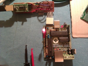
With help from Dr Matt, who held the magic formula of having a 10nF capacitor between #CTS and the Reset pin, I was able to get my breadboard version working, and the following evening I had my stripboard version working (dodgy soldering!)
flickr set: http://www.flickr.com/photos/21085792@N00/sets/72157626929358874/
Next step is to add a 6 pin header for programming the Nanode.

The FTDI connector pins on the Nanode, left to right when looking at the edge with the USB socket, with the usual FTDI cable colours:-
- GND (Black)
- CTS# (Brown)
- VCC (Red)
- TXD (Orange)
- RXD (Yellow)
- RTS# (Green)
These are as labelled on the FTDI cable although the RX and TX need to be swapped (I think!)
So we just need a single extra connection for the 6th pin - keeping it disconnected for now.
14:52, 14 June 2011 (BST) Hooray! The Nanode programming connector now works! The problem was my reading of the pinouts of the FTDI cables which is seemingly different to the Nanode header. I can't imagine how everyone else's FTDI cable works. Never mind!
Here's a blinky for the Nanode using D6 instead of D13...
void setup() {
  pinMode(6, OUTPUT);
}

void loop() {
  digitalWrite(6, HIGH);
  delay(100);
  digitalWrite(6, LOW);
  delay(100);
  digitalWrite(6, HIGH);
  delay(100);
  digitalWrite(6, LOW);
  delay(100);
  digitalWrite(6, HIGH);
  delay(100);
  digitalWrite(6, LOW);
  delay(600);
}