Superbox CNC Router: Difference between revisions
DauntlessA (talk | contribs) Major additions, particularly: Removing details on joints in homing (since joint mode is no longer accessible), expanded sections on 'setting zero' and 'running a job'. |
m Add risk assessment |
||
| (2 intermediate revisions by one other user not shown) | |||
| Line 7: | Line 7: | ||
|induction=No | |induction=No | ||
|team=CNC | |team=CNC | ||
|riskassessment=Team:CNC/Risk Assessments/CNC Routing | |||
}} | }} | ||
| Line 334: | Line 335: | ||
The above details cover touching off X, Y and Z positions, but in fact the rotation of the work relative to the machine's axes is important as well, especially when accuracy is required. | The above details cover touching off X, Y and Z positions, but in fact the rotation of the work relative to the machine's axes is important as well, especially when accuracy is required. | ||
Rotation about the X and Y axes is often constrained by clamping the work down to a relatively flat surface (this is the issue occurring when people talk about vice jaw lift). | Rotation about the X and Y axes is often constrained by clamping the work down to a relatively flat surface (this is the issue occurring when people talk about vice jaw lift). | ||
Rotation about Z (i.e. the work orbiting | Rotation about Z (i.e. the work orbiting a point in the XY plane) can be set (among other methods) by using the machine to cut a straight edge in some stock to locate the work against, or sweeping the part with an machine-mounted indicator and tapping the work in, or even taking measurements of two points, doing some calculations and rotating the machine's coordinate system to match the part (if you do this, PLEASE set rotation back to 0 afterwards, or you may ruin the next user's part). | ||
| Line 358: | Line 359: | ||
Finally, there is a 'feed hold' button in the GUI. This is essentially a pause button, pausing axis motion until the same button is pressed again to resume (don't press 'Play' to resume or the program will start again from the top). This does NOT turn off the spindle. If you do pause the machine and turn off the spindle manually with its switch, it goes without saying that it needs to be turned back on and allowed to get back to speed before cutting is resumed. | Finally, there is a 'feed hold' button in the GUI. This is essentially a pause button, pausing axis motion until the same button is pressed again to resume (don't press 'Play' to resume or the program will start again from the top). This does NOT turn off the spindle. If you do pause the machine and turn off the spindle manually with its switch, it goes without saying that it needs to be turned back on and allowed to get back to speed before cutting is resumed. | ||
If you need to briefly leave the machine unattended partway through a long program, this is the way to do it (ideally with some indication that the machine is paused and should not be touched)! | |||
Keeping your cursor over either feed hold or stop is probably a good idea when the machine is cutting! | Keeping your cursor over either feed hold or stop is probably a good idea when the machine is cutting! | ||
Latest revision as of 22:26, 28 March 2025
| Superbox CNC Router | |
|---|---|
 | |
| Manufacturer | Marchant Dice |
| Obtained | Acquired from Wireless Things after their close (2016) |
| Location | CNC Area |
| Team | CNC |
| Induction Required | No |
| Risk Assessment | Yes, see the assessment |
| Tools: all pages • list • Power Tools • Broken tools {{}} | |
The Superbox CNC Router (aka CNC Mill) is a versatile tool that can cut a wide variety of materials. The machine has 3 degrees of freedom meaning that unlike the Laser Cutter, which can only cut 2D Shapes, the CNC Mill can carve shapes in 3 dimensions if you can provide the tool paths to drive it. It does not require an induction to use, but help is available if you need it! Contact the #CNC channel on Discord if you need help.
We operate a bring-your-own-bits policy for this machine due to the high likelihood of broken tools. Links to buy tools are available on the Suppliers page.
Overview
| Parameter | Value | ||
|---|---|---|---|
| Working Area | X | Y | Z |
| 348mm | 350mm | 115mm (150mm Z Travel but only unto 90mm Y overhang) | |
| Maximum Feed Rate | 2000mm/min (XY) 1000mm/min (Z) | ||
| Spindle | Kress 1050 FME | ||
| Control Software | LinuxCNC | ||
| Control Interface | Gmoccapy | ||
| Control Hardware | Superbox 2.8 | ||
Software
LinuxCNC, with the Gmoccapy interface, is the control software that we use to drive the tool. There is a dedicated computer hooked up to the machine for this purpose.
LinuxCNC reads G-Code in the .ngc format. You can use any CAM (Computer Aided Manufacture) package you like to create G-Code at home or on the computer opposite.
Slightly older video about Gmoccapy but might be useful to familiarize yourself: https://www.youtube.com/watch?v=O5B-s3uiI6g&t=219s
Y Axis
The machine has a dual Y axis stepper setup, where two stepper motors at either side are used to drive the Y axis. The machine is therefore using a development version of LinuxCNC 2.8.
The Y axis is also fitted with two stops, the second of which was designed and added by the hackspace to help in keeping the Y axis homing square to the X axis (so when you try and cut a rectangle you don't end up with a slight parallelogram instead!)
Spindle

The Spindle is a Kress 1050 FME. Its speed is manually controlled via the black dial on the top. It is a good idea to set the spindle speed whilst the spindle is stopped to minimize the operator reaching over the moving machine.
Power to the spindle is controlled via LinuxCNC during operation; It will spin up when it receives an M3 S1 G-Code command to start it, and stop when it receives an M5 command. There is a slide switch on the side of the spindle that should be left on at all times. If it is turned off the tool will simply crash into the work piece without cutting.
| Dial | RPM |
|---|---|
| 1 | 10,000 |
| 2 | 12.600 |
| 3 | 17,000 |
| 4 | 21,000 |
| 5 | 25,000 |
| 6 | 29,000 |
There is a spindle lock button to aid with tool and collet changes.
Collets
We have the following collets available, currently stored underneath the monitor for the CNC Computer.
| 1/8" (3.175mm) |
| 4mm |
| 6mm |
| 8mm |
| 10mm |
(This is mainly a problem when trying to use drill bits, where the shank is often the same diameter as the tool. To get around this, source suitable drill bits (example) or bore your holes instead)
Bed
The bed is made from PT25 profile Aluminium at 375mm wide
This gives slots every 25mm for fixing.
We have a small selection of T-Slot nuts that will slide into these channels to provide clamping anchors. The T-Slot nuts will accept an M6 bolt.
Suitable materials
- Most woods
- Most plastics
- 6082 T6 Aluminium with caution
- Brass with caution
- Others with extreme caution
This machine is best suited to soft materials due to its aluminium frame. Soft woods, such as Pine, can be cut easily with great results. Plywood is a cheap material that can be used to produce simple profiles quickly but is likely to chip if you are doing any moulding operations. Other materials may work with extreme caution; YouTube videos are a good place to start.
If you are planning to cut hard materials, have a couple of spare tools to hand as you will no doubt break one. Also, do not underestimate the amount of time it will take to clean the machine after the cut. Please leave the machine as you would like to find it.
Generating G-Code
To control the tool you will need to feed it instructions. This is done through G-Code! There are more than a few options available for generating G-Code. Each has different pros & cons and each requires a different set of skills to operate. LinuxCNC reads G-Code in the .ngc format.
-
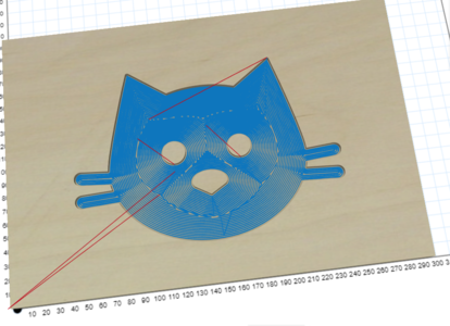 Tool paths from Easel
 -
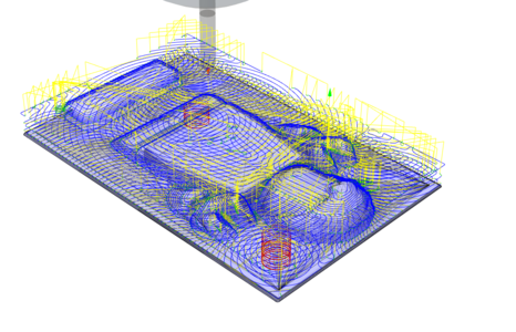 Tool paths from Fusion 360
For Beginners
Inventables' Easel is a 2.5D online CAM package that has a friendly GUI and only requires two small alterations to the code to enable it to function with our machine.
For Enthusiasts/ Advanced Users
Fusion 360 is a great free software package that has tons of CAM functionality built in. Once you have set up your tool paths using the CAM tools in Fusion you can export the setup using the "LinuxCNC (EMC2) / linuxcnc" post processor built in to Fusion 360.
A good place to start if you're not sure with CNC programming via Fusion 360 is the NYCCNC Youtube channel.
A model of the Kress Collet Nut is here for use in Fusion 360 CAM as a tool holder.: File:Kress Holder.zip
(Instructions for installing The tool library in Fusion 360 can be found here.)
Modelling the tool holder in CAM can aid visualisation and help prevent collisions between the collet nut and workholding, if the workholding is also modelled.
If you want to understand what each line in your program does, refer to the LinuxCNC "G-Code" Quick Reference.
NC Viewer is a useful website to plot programs and analyse them line-by-line.
File Structure
A typical G-Code file might look like this. This may be useful if you want to understand what modifications you need to do to make your program run.
%
(My Awesome Part)
G90 G94 G17 G21
G0 G53 Z0
M3 S1

-axis movements to cut part-

M3 S0
G0 G53 Z0
M30
%
A breakdown is below.
We give the machine a number of 'sanity' G-Codes at the start of the program to ensure parameters are correct.
We then give commands to start the spindle, and safely move to the start of the cut.
At the end, we give the machine commands to leave the cut, turn off the spindle and end the program.
% |
Standard starting character |
(My Awesome Part) |
You can add Comments to your file! |
G90 G94 G17 G21 |
Sanity G-Codes (absolute positioning, units per minute, select XY plane, units in mm) |
G0 G53 Z0 |
Rapid move to top of Z travel |
M3 S1 |
Start Spindle (speed set on dial, rpm value here may be useful as reminder, though) |
G54 |
Use G54 Coordinate system, sanity G-Code |
-axis movements to cut part-
M3 S0 |
Stop Spindle |
G0 G53 Z0 |
Rapid move to top of Z travel |
M30 |
Program End |
% |
Standard ending character |
In addition, a feedrate must be declared at the top of the file before a G1 command (move with a specified feedrate, used for cutting) can be used.
To do this, add a line before and use this to declare a feedrate. F1500 means a feedrate of 1500mm per minute.
Operation Instructions
Safety
This is a dangerous tool and should be treated as such. Your safety is your own responsibility. As a guideline, you should wear as a minimum:
- Safety Glasses
- Flying Chips, Broken Tools & loose workpieces are all possibilities
- Ear Defenders
- This machine is seriously loud, you must sit very near to it to monitor the job while it’s running and it’s not uncommon for a cutting cycle to be 30 minutes or longer. Hearing damage is a very real risk. Make sure you also warn others in the CNC room of this too.
Loading your tool
When loading your tool you need to ensure that as much of the shank is contained within the collet as possible. The only exception to this rule is if the job you are running requires a deep cut; then you will need the tool to stick out further.
The video below shows how to load a tool:
Turn on
Turn on the monitor, PC and Control box
The PC should auto boot into linux and automatically log in to the nottinghack account, if not the password is hackspace
Once in you should see the following desktop, click on the Launch CNC icon to start LinuxCNC
-
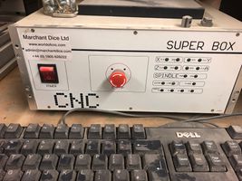 1. Turn on the PC & Control Box
 -
 2. Click 'Launch CNC' (Penguin Icon)
 -
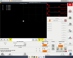 3. Your should now see the
Gmoccapyinterface to LinuxCNC


Emergency Stops
Make sure the physical eStops have been cleared by twisting them and check that the eStop light on the control box is out.
Reset The LinuxCNC software eStop by clicking the red hand icon in the top right corner.
Turn on the machine in the software by clicking the power button just below the software eStop.
The Interface should look like this:
-
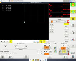 4. Software ready to home

Homing
Homing is the action of setting where the machine's origin is in space. Or, more simply put, telling each joint that makes up the machine where zero (and hence the range of positions for the axis) is. This is done by slowly approaching a 'homing switch', whose trigger signals to the controller that the joint position should be set to a specified value.
This allows 'soft limits' in axis positions to be established, so the controller does not allow you to 'crash' an axis by exceeding a soft limit. In addition, it allows (within the repeatability of the homing switches) repeatable movements to the same location in the work area. In practice, this means that the location of objects such as work and vices stays the same in machine coordinates, allowing you to continue machining across restarts of the controller without having to touch off your work again.
The machine starts up with the joints unhomed. It is not possible to jog the axes or otherwise use the machine until you have homed it, to avoid a crash or misaligning the Y axis.
(While in theory the controller could simply write its coordinates to file on shutdown and retrieve them on startup, this is not a complete solution for stepper motors, as their exact position is determined by microsteps which are lost when the stepper motors lose power. In addition, if joints are moved when the power is off, their new position will be determined when the machine homes)
To home the machine, first open the Home menu click the icon in the bottom left corner of the interface. (Target and three arrows). In the bottom menu now click the Home all Icon (far left)
The order in which the axes are homed is first Z, then X and Y simultaneously. Homing Z first lifts the Z axis to the top of travel, avoiding obstacles like vices.
Once all the joints have been homed (signified by the display of axis positions changing from red to green) the machine should now be ready to go.
-
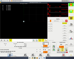 5. Open the Homing menu (Target and three arrows icon)
 -
 6. Home all joints
 -
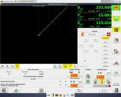 7. Machine ready to go


The machine should be rehomed in instances where it is suspected that any of its axes have lost their position. This primarily occurs due to the machine's stepper motors failing to make a requested step due to insufficient torque (such as when the machine is crashed or too heavy a cut is taken), or power is lost to the stepper motors (such that the stepper motor rotors move to the nearest full step, likely causing small movements).
As the machine uses open loop stepper motors with no feedback, LinuxCNC is UNABLE to provide any indication of a loss of position due to requested steps not being taken (following errors are only generated as a result of issues with software step generation, where the controller knows it has failed to generate the requested steps). Therefore, a loss of position could cause a further damaging crash (such as into the frame, bed, homing switches or part) if the machine is not rehomed. If you have any doubts, please rehome the machine.
Due to the slight loss of position when a loss of power to the stepper motors occurs (when an estop is pressed, or power is toggled in the GUI or with the controller's power switch), LinuxCNC forces you to rehome the machine when this occurs.
Loading G Code
After you have homed the machine using the instructions above, Click "Enter auto mode to run programs" on the right hand side menu.
On the bottom row of icons you will see a folder icon. Click this to navigate to your ".ngc" G-Code file (the default location is JARVIS).
-
 8. Enter Auto Mode
 -
 9. Browse to G-Code file


Setting Zero
G54 is a coordinate system that is offset from the machine coordinate system (which is called G53). I.e. when you set a position as zero in G54, the CNC is storing this zero position as offsets in X, Y, Z from the machine's G53 origin.
It is used to tell the CNC software where you have secured your workpiece to the table (Set Zero), so it needs to be set before any program is run! The position of the G54 origin should match the origin in your CAM software.

To set it,
- Enter Manual Jogging mode by pressing the appropriate button on the right hand side or pressing F3 on the keyboard.
- Open the probing menu by clicking on the blue icon at the bottom.
- Use the control arrows to move the gantry so that the centre of the tool is sitting on the point where (X,Y,Z) is (0,0,0) on your CAD model. It is easier to probe one datum at a time. E.g. X, then Y, then Z
- On the bottom bar, press "X=?", "Y=?" OR "Z=?" depending on the direction you have probed and set the zero point.
You can of course locate using any position on the part (or any position of the tool) as long as the position you enter for the tool tip matches the position in CAM.
If you're cutting a part from sheet, you may not need to be very accurate in setting XY, and might be able to set them by eye (as is often done on the laser cutter). If you need to touch off more accurately, the above principle also allows you to touch off by using an object of a precisely known thickness as a spacer (such as the shank of another endmill) between the tool and a surface on the work, rather than trying to touch a surface on the work directly.
To do this, move the axis until you find a position where you can feel slight resistance when moving the spacer between the work and the tool. If the spacer is loose or does not fit, you are too far away or too close, respectively. To avoid 'pinching' the spacer, you can hold it out of the way when you are moving the axis closer to the work, sweeping it back and forth between movements until the correct position is achieved. Use sequentially smaller movement increments to 'zone in' on the correct position.
Accounting for the diameter of the tool when setting XY can be done by adding or subtracting (depending on whether the tool tip is in a negative or positive position respectively compared to the position in the axis you're probing) half the tool's diameter into the probing menu box. Check its right before running any G-Code by jogging the tool to X=0, Y=0 at a safe Z height; the centre axis of the tool should be over the datum point.
Note that many tools don't have the nominal radius at every point (looking at any tool with flutes will confirm this!) or do not have one at all (are tapered). You can get around the former issue by spinning the tool to expose the maximum radius, or both issues by using a dummy tool of a precise diameter such as a dowel (or even an endmill with a long enough shank inserted into the collet the wrong way up, making sure you aren't clamping on empty space or the flutes). The dummy tool can have a different diameter to the real tool as long as you use this diameter when you touch off.
The above details cover touching off X, Y and Z positions, but in fact the rotation of the work relative to the machine's axes is important as well, especially when accuracy is required.
Rotation about the X and Y axes is often constrained by clamping the work down to a relatively flat surface (this is the issue occurring when people talk about vice jaw lift).
Rotation about Z (i.e. the work orbiting a point in the XY plane) can be set (among other methods) by using the machine to cut a straight edge in some stock to locate the work against, or sweeping the part with an machine-mounted indicator and tapping the work in, or even taking measurements of two points, doing some calculations and rotating the machine's coordinate system to match the part (if you do this, PLEASE set rotation back to 0 afterwards, or you may ruin the next user's part).
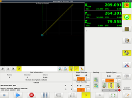
If everything has been set correctly, you should see the preview of your G-Code shift to the correct location.
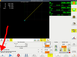
For each axis, the G-Code preview should show the minimum and maximum limits in G54.
If you are uncertain of whether your program will collide with an obstacle, it might help to jog around the obstacle and compare the machine's positions in the backplot with the positions in your program.
Running a job
Once everything is set up (see the checklist below) simply press the Play button located in the "Auto Mode" menu to start. When the machine is running, you should pay attention to what is happening and be ready to intervene if something goes wrong. Remember, even though the computer is doing the cutting, YOU are the operator! Therefore, you must not leave the job unattended, and be ready with the Hoover as a lot of sawdust can be produced.
There are a few buttons to be aware of when the machine is cutting. The most important are those which pause or stop the machine.
If you feel that the machine needs to be stopped as soon as possible, do not hesitate to use a physical emergency stop. This can be hit easily, and will bring the axes and spindle to a stop. The estop will need to be reset before further action can be taken. Note that resetting the estop does not cause the program to continue execution.
There is also a 'stop' button in the GUI. This simply ends execution of the program at the current point, and issues a program end command to turn off the spindle. There is nothing to reset.
Finally, there is a 'feed hold' button in the GUI. This is essentially a pause button, pausing axis motion until the same button is pressed again to resume (don't press 'Play' to resume or the program will start again from the top). This does NOT turn off the spindle. If you do pause the machine and turn off the spindle manually with its switch, it goes without saying that it needs to be turned back on and allowed to get back to speed before cutting is resumed.
If you need to briefly leave the machine unattended partway through a long program, this is the way to do it (ideally with some indication that the machine is paused and should not be touched)!
Keeping your cursor over either feed hold or stop is probably a good idea when the machine is cutting!
The other GUI options to be aware of are the rapid and feed override sliders. These control the speed of G0 non-cutting moves at maximum speed, and cutting moves with a specified feedrate respectively.
Generally, it's good practice to keep the rapid override low until you're confident in the program.
Unfortunately, Autodesk Fusion outputs most G0 moves as G1 in the free version. If this affects you the rapid override will have no effect on most repositioning moves, and you will need to use the feed override to control the speed of all moves. This isn't ideal as a blanket setting, since reducing the cutting feedrate will reduce the tool's feed per tooth if you don't drop the spindle speed to compensate.
If you are running multiple programs with multiple tools, there are a few things to remember to avoid crashes and ensure the machine performs as you planned.
Have you:
- Loaded the new programs? (don't accidentally run the previous programs)
- Loaded and tightened the new tool? (don't accidentally run the previous tool)
- Set the position (tool length) of the new tool? (touched off the new tool in Z)
- Set the spindle speed for the new program using the spindle dial, and ensured that the spindle power switch is on? (don't accidentally run the previous spindle speed or run with the spindle off)
Example Projects
If you have a project that uses this tool please add it to this list. It would be great to see what other people are using the CNC Mill for!
-
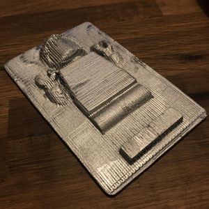 Han Solo in Carbonite CNC
 -
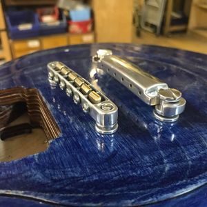 Les Plywood Tune-O-Matic Bridge Hardware
 -
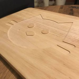 CNC Workshop for Beginners
 -
 WW2 Prop Gold
 -
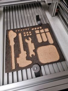 CNC Tool Storage
 -
 Flip Milled Makercoin
 -
 CNC UK Heightmap
Maintenance
Occasionally the CNC Router will break down and require maintenance. If you're not sure who to ask for help, the #CNC Discord group is the right place to go.
Some maintenance notes are recorded on the wiki here: Superbox CNC Router Maintenance includes information about replacing the Super Box's fuse.
See also
- CNC Workshop for Beginners - workshop designed and run by Dan Spencer
- Suppliers - Milling
- Contour ShuttleXpress - Pendant Jog Shuttle
- New CNC PC Pledge - successful pledge drive for better computer
Resources
-
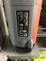 Kress Rating Plate
 -
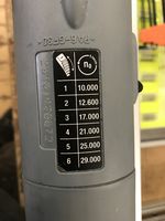 Kress Speed Plate

