TagTool: Difference between revisions
No edit summary |
m Danspencer101 moved page Project:TagTool to TagTool over redirect |
||
| (3 intermediate revisions by 3 users not shown) | |||
| Line 55: | Line 55: | ||
</gallery> | </gallery> | ||
The port could be prettier but I'm happy enough with it. There's no clearance above the Arduino headers so the wires go straight into the headers and are protected from the | The port could be prettier but I'm happy enough with it. There's no clearance above the Arduino headers so the wires go straight into the headers and are protected from the PCB above with some insulating tape. | ||
[[Category:Projects]] | |||
[[Category:Projects (complete)]] | |||
Latest revision as of 11:58, 5 February 2019
I just received my haul of 10k slider potentiometers
http://www.tagtool.org/wp/2008/02/22/tagtool-mini-tutorial/
http://www.instructables.com/id/How-to-build-a-Tagtool-Mini/
Hacked Video Mixer

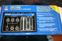
Last week I picked up a free video mixer that was in the Hackspace donations box. It has some sliders, some rotary pots and a button, all wonderfully boxed in a bespoke case. Sounds like a TagTool hack opportunity to me!

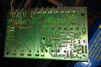
Upon opening it up I see that there is a small amount of space under the circuit board. I don't want to remount any of these nice solidly mounted components so I'll try to work with it. I see a good space that might hold a complete Arduino. It is such a nice box that I think I will sacrifice my Arduino Duemilanove since I need USB serial comms with the PC and I want this to be a simple repurposing example.

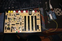
I suspect that the device might be fully functional so I don't want to do anything destructive: I'll make every alteration easily undoable. Here I've soldered a few wires in place: a ground plane, VCC to the tops of 3 of the sliders, and a wire to each of the 3 wipers. The sliders for audio have different characteristics to the video mixer slider so I'll just use those 3 to start with. Next I'll hook up 3 of the rotary pots totalling 6 as required by the tagtool (and supported by the Arduino).

The test sketch for these first 3 sliders is pretty simple: just read the 3 analogue inputs and print to the hardware serial.
void setup() {
  Serial.begin(9600);
}

void loop() {
  int a0 = analogRead(A0);
  delay(10);
  int a1 = analogRead(A1);
  delay(10);
  int a2 = analogRead(A2);
  // outputValue = map(sensorValue, 0, 1023, 0, 255);
  Serial.print("sensors: ");
  Serial.print(a0);
  Serial.print(" ");
  Serial.print(a1);
  Serial.print(" ");
  Serial.print(a2);
  Serial.println();

  delay(500);
}
Next, it's Dremel time! The USB port need to see the light of day. Shortly after starting I hear a complaint from the missus to shut up the noise as it's after 10pm! I continue with a tiny file and craft knife!
-
Arduino location
-
USB hole required
-
USB rough cut
-
USB nearly right
-
USB done
-
USB could be tidier!
-
USB from inside
-
USB with cable
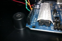
The port could be prettier but I'm happy enough with it. There's no clearance above the Arduino headers so the wires go straight into the headers and are protected from the PCB above with some insulating tape.


