MLRS Control Panel
| MLRS Control Panel | |
|---|---|
 | |
| Primary Contact | Msemtd |
| Created | 25/05/2015 |
| Status | In Progress |
| Type | Members Project |
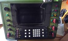
I have obtained two non-functional decommissioned Lockheed Martin M270 MLRS Fire Control Panels (don't ask!*) and I plan to change their purpose slightly from destroying things (up to 40 miles away!) to dispensing salad ("Rocket Launcher" - geddit?)
All the components (on the primary unit) that do self-test seem to be working: the lamps, etc. The control PC hard drive is missing (bah!).
New Purpose: Salad Launcher
This is all going to be new-build stuff which I plan to do for the 2015 Crap-o-thon. Projectile work is fun and there are many options but my goals are all about the salad and reusing certain bits of kit I have found. The replaced Raspberry Pi B+ from the Bartop Defender is a good base processor and a fake Chinese Arduino Due for all the I/O is a good re-use too. I have a few flight cases (all skip finds) that will be good for taking the kit to events, and I plan to use at least one of those as the body for the MLRS rocket unit.
Lettuce as a projectile
Lettuce and other salad leaves are entirely unsuitable for use as projectiles. However, weaponising otherwise healthy food is my life's work.
And to my detractors and would-be critics: you have such short memories! Do you not remember the glorious successes of my War-Raisins and the Tactical Combat Bagel? As a continually failing vegan (failed again today - damn that slightly mouldy cream cheese that my kids left to go off in the fridge) I have all the necessary skills to transmogrify bad into good and then default back to bad.
Deadly Portion Size
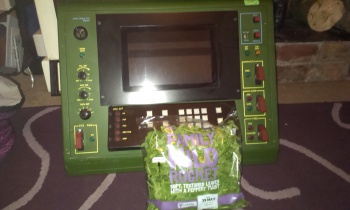
Rocket has low density - as you see in the photo above, a handful portion has a mass of about 10g. Now this is only one of your 5-a-day and we want to promote diversity in the diet so I think it's fine to add a little something to the mix to increase the chances of lethal engagement.
Paul Newman's Balistic Vinaigrette
"A knock-em-dead dressing that’s perfect on any salad. Enjoy!"
http://www.newmansown.com/products/newmans-own-balsamic-vinaigrette-dressing/
Well, the words of the man himself are good enough for me. We shall therefore be adding a tasty battlefield dressing to our projectiles.
Flatbread Targets
The use of Hummus on an enemy is forbidden under The Geneva Conventions: recently ratified and codified into international treaties that classify the use of this tasty and nutritious dip as a form of bio-chemical warfare. Due to this change we find large battlefield stockpiles of Hummus at various flatbread bunkers. Our primary objective is to target these illegal weapon facilities.
The Hardware
One of the main decisions to be made is what parts of the original hardware to retain in the design and what to strip out. Since I currently have two units (one a PC-based console and one a Motorola 6809 terminal) I will probably retain the common hardware and abandon the processors. The I/O board on the PC unit is nice and it does give us a lot of clues about the various bits and pieces but I think I'd like to drive everything from a very simple PCB.
Plasma Display
The displays are the real beauty of these units and something I would not want to abandon. Driving the displays is my main focus at the start of the project; the switches and lamps should be trivial; the keypad might need some investigation!
- 640 x 400, orange, high voltage, what's not to like?
- Densitron International PLC DT63-J
- Also a Densitron DT61 in the second unit
- some mention here http://www.datasheetarchive.com/dl/Scans-049/DSADA001035.pdf
- some info (mostly sales) https://archive.org/stream/Densitron-ProductGuideOCR/Densitron-ProductGuideOCR_djvu.txt
- possible lead: https://archive.org/stream/Densitron-RS232ControllerCardFor400x600LCDandPlasmaDisplaysSPX20SeriesOCR/Densitron-RS232ControllerCardFor400x600LCDandPlasmaDisplaysSPX20SeriesOCR_djvu.txt
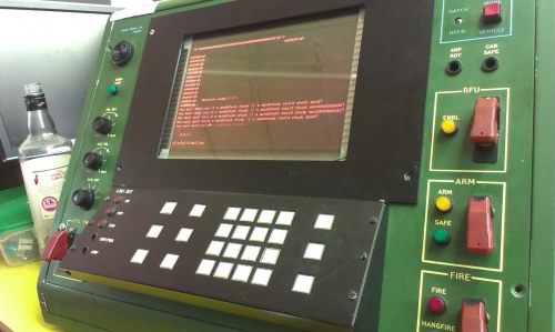
I spent a couple of evenings working on the second unit and focussing on the plasma screen: it has a built-in VT320 terminal -- or is it more correct to say that it is a VT320 terminal? Anyhow, I failed to get anything up on the screen. I removed the bezel that masked off the top line (which took a bit of dismantling - I should have took photos!) and then the glorious blinking orange block cursor could be seen. The high pitched noise from the screen was really quite apparent but not too unpleasant to my middle-aged, gig-battered ears.
My terminal test setup was just my laptop with a Prolific USB-Serial adapter and a 9-way to 25-way D connector into the "host" port on the screen unit. With a bit of tty help (thank's Hazel!) I tried all the usual baud rates and a few other settings but nothing appeared on the screen. Now I had been told by one of the engineers who worked on the project that the system just talked to the screen over RS232 but not exactly how! I remember from my years working on the various VT terminals on the VAX at Trent Poly that there is a setup mode to most terminals. There is also a keyboard socket on the back of the unit which is a 5 pin DIN. I tried an old AT PC keyboard and didn't expect it to do anything but was still a bit disappointed when nothing happened!
Next leads: -
- is the voltage too low for a true RS232 input? +/-12v is required but these little USB adapters don't really do everything to spec
- if so then a more standard device might do the trick
- when I dismantled the display to remove the bezel I could see the connections on the 25-way D socket
- take pictures, buzz them out - see what lines are expected, RTS/CTS/CD, etc.
- find more info about the VT320 driver board in the unit
- SPX 20 interface: http://www.datasheetarchive.com/dl/Scans-049/DSADA001035.pdf
- I'm informed by one of the engineers that we are dealing with a simple 9600 8-N-1 over RX, TX, GND
Update --Michael Erskine (talk) 10:55, 4 June 2015 (UTC)
- Finally have text going to screen! Glorious orange glow!
- A convoluted mess of cables just to map 3 wires on the serial port. This will obviously be rationalised to a simple cable.
- As DTE, the terminal receives on pin 3 (http://en.wikipedia.org/wiki/Data_circuit-terminating_equipment) so our end must act as DCE or just crossover from our pin 2
- Odd cursor handling for carriage returns and line feeds
- VT320 but using ANSI terminal type in minicom allows cursor movement
- various escape sequences need to be understood! http://web.archive.org/web/20090301231831/http://www.cs.utk.edu/~shuford/terminal/ansi_x3_64.txt
The SPX-20 blurb describes a terminal setup mode but I have yet to find it. I doubt it is a standard VT-320 feature as it will have proprietary features. Anyhow, these devices have been powered down for years and may well be using default values.
Tested escape sequences: cursor keys work (minicom ANSI mode) as does the home key so they could be used where required.
- ESC [ = CSI
- CSI 2 J = erase screen: very useful
- CSI A = cursor up
- CSI B = cursor down
- CSI 7 m = inverse video
- CSI 0 m = normal video
- CSI 4 m = underline on
- CSI 5 m = blinking on: cool effect!
- CSI Pn ; Pn H = goto X,Y
- ESC c = reset terminal: also very useful
Pi and Arduino
- Clear cut roles
- Pi selection: I have a number of Pi units to choose from
- Arduino selection: Due? Mega? bare ATMEGA328P?
- again I have a number to choose from (perhaps too many!)
- 3.3v operation of Due may be useful when interfacing to Pi
- OK, Due it is: http://www.arduino.cc/en/Main/ArduinoBoardDue
- use this beastie: http://www.robgray.com/temp/Due-pinout-fillable-form.pdf
- comms to terminal through JungleTronics MAX3232 DB9 RS232 to UART cable
- another similar $1 RS232-UART device in post from China
- All I/O (switches, lamps, keypad, buzzer, etc.) through Arduino
- also Serial abstraction? Build for Pi or build for PC (GPIO UART vs USB)
- any Pi GPIO at all? Other than UART? Perhaps small power-down circuit
Little Perl script to drive display
Simple Arduino sketch allowing pass through of serial data from PC to terminal
You'll note that I've #def'ed out the pass-through of serial data back from the terminal: I've found that the Perl script hangs after a few sends which may be because I'm not reading from the port. I'm not too worried about this right now but I am interested in what the terminal can tell us about its status.
Considering Java on the Pi for the control program as Eclipse is the most productive IDE I have ever used. The JSSC serial library needs a good testing! Alternatives still include Device::SerialPort under Perl and a nice C program!--Michael Erskine (talk) 10:14, 20 June 2015 (UTC)
The Java version pre-installed on Raspbian (Oracle JRE7) seems fine...

Internal power sources: AC Mains + various DC
- Examine power supply and establish specs
- Coutant model HSG40-32 P/N G90109 Max. 40W
- http://us.tdk-lambda.com/lp/products/legacy_1.htm
- DC outputs: P1 = DC COM, P2 = ???, P3 = +5V/3.5A, P4 = -12V/0.25A, P5 = +12V/1.5A
- Mains relay control?
Lamps and Switches
Another cool thing about this console is those lovely launching controls.
There are 4 fancy-ass switches with safety covers: -
- SYS PWR = "System Power": a simple on/off switch with a green indicator labelled "ON"
- RFU = currently unknown (I shall have to dig out some info) another simple switch with green indicator labelled "ENBL" which must mean "Enabled"
- ARM = I'm guessing "Armed": this switch can only be in the up position when the sprung cover is open: closing the cover pushes the switch into the down position which I assume is the safe position. There are two indicators here: a red one labelled "ARM" and a green one labelled "SAFE" - easy to guess what they mean!
- FIRE = "Fire!": this is a cool switch that is sprung for monentary contact - it is so ergonomically lovely to use! And deadly! There are two red indicators labelled "FIRE" and "HANGFIRE". I'll try to find out what their official usage is.
Other thingies
- HELP
- MOVE VEHICLE
- HATCH OPEN
- SRP RDY
- CAB SAFE
Handily the switches and lamps on the right hand side (of the PC unit anyway) all go to a pair of headers on the I/O board nicely labelled "LAMPS" and "SWITCHES". The lamps appear to be driven with ULN2803A devices (https://www.ti.com/lit/ds/symlink/uln2803a.pdf) so they might be pretty heft in current drain! Testing required!
RHS Switches Connector CN6 buzzed-out: -
- Pin 1 = GND for 2, 3, & 4
- Pin 2 = HELP
- Pin 3 = MOVE
- Pin 4 = FIRE
- Pin 5 = N/C
- Pin 6 = N/C
- Pin 7 = GND for 8, 9, & 11
- Pin 8 = HATCH (up posn)
- Pin 9 = RFU
- Pin 11 = ARM
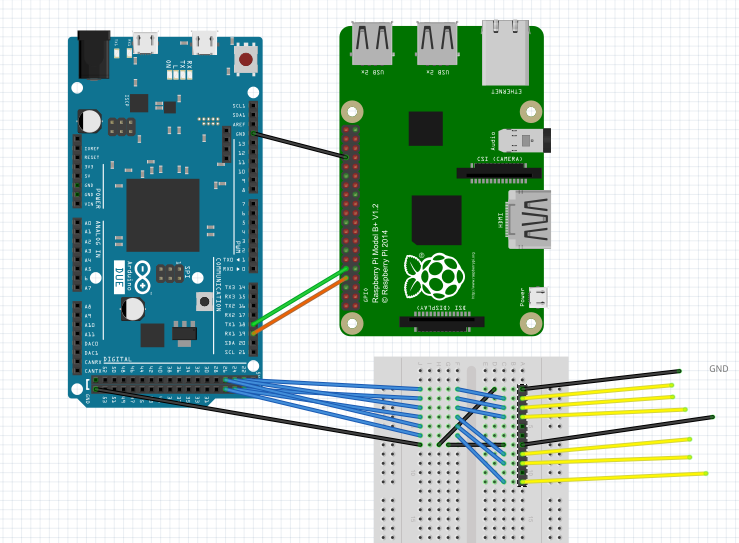
Simple hookup of Pi and Due for first bank of inputs: -
I/O Board misc
- IC4 = 74HCT08N. Quad 2-input AND gate
- IC3 = NE555P (I'm guessing for alarm buzzer)
- IC5 = SN74HC74N
other
- brightness pots
- brightness switch - 6 inputs
- buzzer
- display relay
Actual Launching
I'd like to go with gas propelled and YouTube is crammed full of various air launching builds. The practicalities for this project are going to need multiple launch capability (the "ML" in MLRS). Electronic control is a must so those relay sprinkler release valves look like the thing: -
Interaction with the FCP
The main "theatre" of the project will be around the launch sequence as controlled by and narrated back through the Fire Control Panel.
Launch sequence: as you might imagine, on the real MLRS there is a very formal and well defined sequence that the operator must go through with all the appropriate safety checks and measures. We want to emulate some of this procedure.
More Info
Actually these are just training consoles used by the British and Dutch armies. They are true representations of the actual firing control panels though and they are just so well built that it would be such a shame for them to end up in the skip (thankfully I am on very good terms with the guys who clear this stuff and I can get some things put aside for me!)
- http://en.wikipedia.org/wiki/M270_Multiple_Launch_Rocket_System
- Jasmin PLC - find drawings and quiz the retired engineers


