Difference between revisions of "Robot Badge"
(Created page with "This is a guide to making rubber stamps on the laser cutter. == Stuff required == Firstly you will need some laser rubber, which can safely be cut on the laser cutter without...") |
|||
| (42 intermediate revisions by 3 users not shown) | |||
| Line 1: | Line 1: | ||
| − | This | + | {{Project |
| + | |image=File:Robot (22).jpg | ||
| + | |name=Robot Badge | ||
| + | |primary=[[User:Chunky|Chunky]] | ||
| + | |created=24/05/2013 | ||
| + | |completeddate=27/05/2013 | ||
| + | |status=Complete | ||
| + | |type=workshop | ||
| + | |qrmode=1 | ||
| + | }} | ||
| + | == Overview == | ||
| + | These are notes and files relating to the 'Learn To Solder' Robot Badge. This badge kit has been produced to use at events as a simple soldering exercise and promote the hackspace. | ||
| + | This badge was based upon a simple flashing LED badge that was seen at UK Maker Faire 2011 in Newcastle. | ||
| + | This robot shaped badge was designed by [[User:chunky|Matt Little]] based on an idea by Rob Keating from PCB manufacturers, [http://www.beta-layout.com/ Beta Layout]. [http://www.beta-layout.com/ Beta Layout] produced a number of batches of these PCBs for Nottingham Hackspace. | ||
| − | == | + | == Build Instructions == |
| − | + | =Robot/Round Badge= | |
| − | + | <gallery widths=320px heights=320px> | |
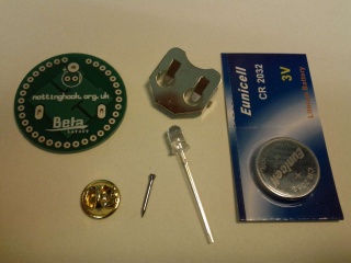
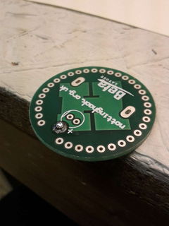
| − | + | File:Robot_(2).jpg|Spread out the parts: PCB, LED, Battery Holder, Battery, Pin, Clasp| | |
| − | + | File:Robot_(5).jpg| | |
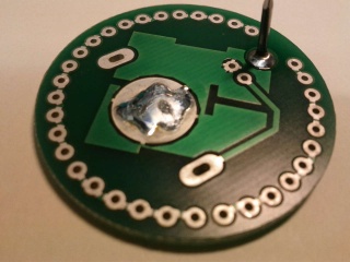
| + | File:Robot_(6).jpg|Apply a small amount of sodler to the battery pad. This raises the pad so it makes a good connection to the battery| | ||
| + | File:Robot_(3).jpg| | ||
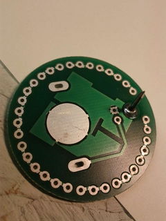
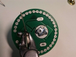
| + | File:Robot_(4).jpg|Put the PCB on the edge of a table and place the pin through. Solder the pin| | ||
| + | File:Robot_(7).jpg| | ||
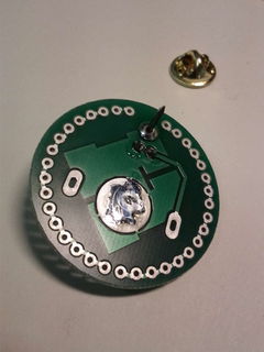
| + | File:Robot_(8).jpg|Solder the LED. Make sure the LED is the correct orientation. The long lead is positive and fits in the hole with the + symbol. | ||
| + | File:Robot_(9).jpg| | ||
| + | File:Robot_(10).jpg| | ||
| + | File:Robot_(11).jpg| | ||
| + | File:Robot_(12).jpg| | ||
| + | File:Robot_(13).jpg|Push the battery clip into the back of the PCB. Make sure the open side is facing downwards so the battery can fit in. | ||
| + | File:Robot_(14).jpg| | ||
| + | File:Robot_(15).jpg| | ||
| + | File:Robot_(16).jpg| | ||
| + | File:Robot_(17).jpg|Push the battery in with the + side face up. And hopefully you should have a flashing badge... | ||
| + | File:Robot_(18).jpg| | ||
| + | </gallery> | ||
| − | + | =SMD Robot Badge= | |
| − | + | <gallery> | |
| + | File:Robot_(19).jpg| | ||
| + | File:Robot_(20).jpg| | ||
| + | File:Robot_(21).jpg| | ||
| + | File:Robot_(22).jpg| | ||
| + | File:Robot_(23).jpg| | ||
| + | File:Robot_(24).jpg| | ||
| + | File:Robot_(25).jpg| | ||
| + | File:Robot_(26).jpg| | ||
| + | File:Robot_(27).jpg| | ||
| + | File:Robot_(28).jpg| | ||
| + | File:Robot_(29).jpg| | ||
| + | File:Robot_(30).jpg| | ||
| + | File:Robot_(31).jpg| | ||
| + | File:Robot_(32).jpg| | ||
| + | File:Robot_(33).jpg| | ||
| + | File:Robot_(34).jpg| | ||
| + | File:Robot_(35).jpg| | ||
| + | File:Robot_(36).jpg| | ||
| + | File:Robot_(37).jpg| | ||
| + | File:Robot_(38).jpg| | ||
| + | File:Robot_(39).jpg| | ||
| + | File:Robot_(40).jpg| | ||
| + | File:Robot_(41).jpg| | ||
| + | File:Robot_(42).jpg| | ||
| + | File:Robot_(43).jpg| | ||
| + | File:Robot_(44).jpg| | ||
| + | File:Robot_(1).jpg| | ||
| + | </gallery> | ||
| − | + | == Parts List - Simple == | |
| − | |||
| − | |||
| − | + | The simple version of the badge is just an LED wired derectly with a battery. A colour changing LED is used to make it a bit more interesting. | |
| − | |||
| − | |||
| − | == | + | {| border="1" align="center" style="text-align:center;" |
| − | + | |Part | |
| − | + | |Details | |
| − | + | |Supplier | |
| − | + | |- | |
| + | |3V Battery | ||
| + | |CR2032 | ||
| + | |[http://cgi.ebay.co.uk/100x-3V-Lithium-CR2032-CR-2032-Cell-Button-Coin-Battery-/290527377732?_trksid=p4340.m263&_trkparms=algo%3DDLSL%252BSIC%26its%3DI%26itu%3DUCI%252BIA%252BUA%252BFICS%252BUFI%252BDDSIC%26otn%3D8%26pmod%3D180649856835%252B180649856835%26po%3D%26ps%3D63%26clkid%3D38332866077294332 eBay 1] Cost: £10 for 100 | ||
| + | [http://cgi.ebay.co.uk/100-x-3V-CR2032-LITHIUM-BUTTON-CELL-BATTERIES-BATTERY-/170602073716?pt=UK_ConsumerElectronics_Batteries_SM&hash=item27b8ad0e74 eBay 2] Cost: £10 for 100 | ||
| + | |- | ||
| + | |Battery clip | ||
| + | |To hold above | ||
| + | |[http://www.rapidonline.com/ Rapid:] 18-3585 Cost: £0.312 100+ | ||
| + | [http://uk.farnell.com/ Farnell:] 908654 Cost: £0.442 100+ | ||
| − | + | [http://www.digikey.com/ Digikey UK:] BK-888-ND Cost: £0.1674 100+ | |
| + | |- | ||
| + | |LED | ||
| + | |5mm colour chaging | ||
| + | |[http://www.rapidonline.com/ Rapid:] 55-1906 £0.4326 100+ | ||
| + | [http://cgi.ebay.co.uk/30-ULTRA-BRIGHT-5mm-COLOUR-CHANGING-RGB-LEDs-5000-MCD-/390125860357?pt=UK_BOI_Electrical_Components_Supplies_ET&hash=item5ad5503605 eBay 1:] Cost: £6.99 for 30 | ||
| − | == | + | [http://cgi.ebay.co.uk/30-ULTRA-BRIGHT-5mm-FAST-COLOUR-CHANGING-RGB-LEDs-/160464005016?pt=UK_BOI_Electrical_Components_Supplies_ET&hash=item255c666798 eBay 2:] Cost: £3.50 for 30 |
| − | + | |- | |
| + | |Pin | ||
| + | |13mm panel pin | ||
| + | |Stones hardware £0.56 for box (100pcs) | ||
| + | [http://www.ebay.co.uk/itm/CHALLENGE-PANEL-PINS-1-2-13mm-/280884702399?pt=UK_DIY_Material_Nails_Fixing_MJ&hash=item4166086cbf eBay 1] £1.60 for box | ||
| + | |- | ||
| + | |Badge Clip | ||
| + | |To fit above pin | ||
| + | |[http://cgi.ebay.co.uk/100-qty-BADGE-CLASPS-BUTTERFLY-CLIPS-MILITARY-CLUTCH-/170391038461?pt=UK_Collectables_Militaria_LE&hash=item27ac18e9fd eBay 1:] Cost: £4.99 for 100 | ||
| + | [http://www.ebay.co.uk/itm/100-qty-PIN-BADGE-CLASPS-BUTTERFLY-CLIPS-SILVER-NICKEL-/180843555570?pt=UK_Collectables_Militaria_LE&hash=item2a1b1daaf2 eBay 2:] Cost: £3 for 100 | ||
| + | |} | ||
| − | + | == Parts List - SMD == | |
| − | + | The SMD version of the badge was designed for more advanced users so they can learn to do surface mount soldering or use an SMD oven. The circuit is a [http://www.talkingelectronics.com/projects/FlasherCircuits/Page83FlasherCircuitsP1.html Flip Flop Two Transistor Flasher]. | |
| − | + | The schematic diagram is here: | |
| − | + | ADD a PHOTO/PDF HERE | |
| − | |||
| − | |||
| − | |||
| − | + | {| border="1" align="center" style="text-align:center;" | |
| + | |Part | ||
| + | |Reference | ||
| + | |Details | ||
| + | |Supplier | ||
| + | |- | ||
| + | |Capacitor | ||
| + | |C1, C2 | ||
| + | |Control flash rate. 10uf used. Size: 1206. | ||
| + | |[http://uk.rs-online.com/web/p/ceramic-multilayer-capacitors/7407546/?searchTerm=7407546&relevancy-data=636F3D3126696E3D4931384E525353746F636B4E756D6265724D504E266C753D656E266D6D3D6D61746368616C6C26706D3D5E5C647B367D247C5E5C647B377D247C5E5C647B31307D2426706F3D313426736E3D592673743D52535F53544F434B5F4E554D424552267573743D373430373534362677633D4E4F4E4526 RS: 740-7546] | ||
| + | [http://uk.farnell.com/multicomp/mcca000600/mlcc-1206-x5r-6-3v-10uf/dp/1759483?Ntt=1759483 Farnell: 1759483] | ||
| + | |- | ||
| + | |Resistor | ||
| + | |R2, R3 | ||
| + | |Control Flash Rate. 100k used. Size: 1206 | ||
| + | |[http://www.rapidonline.com/Electronic-Components/100K-1206-5-Chip-Resistor-Pack-of-100-72-1437 Rapid: 72-1437] | ||
| + | [http://uk.farnell.com/multicomp/mcmr12x104-jtl/resistor-anti-sulfur-100k-1206/dp/2073883?Ntt=2073883 Farnell: 2073883] | ||
| + | |- | ||
| + | |Resistor | ||
| + | |R1, R4 | ||
| + | |Limit LED current. 0 ohm with 3V battery. Size: 1206 | ||
| + | |[http://www.rapidonline.com/Electronic-Components/0R-1206-5-Chip-Resistor-Pack-of-100-72-1207 Rapid: 72-1207] | ||
| + | [http://uk.farnell.com/multicomp/mcmr12x000-ptl/resistor-anti-sulphur-0r-250mw/dp/2073874?Ntt=2073874 Farnell: 2073874] | ||
| + | |- | ||
| + | |Transistor | ||
| + | |Q1, Q2 | ||
| + | |NPN type. S0323. BC817W used. | ||
| + | |[http://uk.farnell.com/nxp/bc817w/transistor-npn-45v-sot-323/dp/2114873?Ntt=BC817W Farnell: 2114873] | ||
| + | |- | ||
| + | |LED | ||
| + | |D3, D4 | ||
| + | |Red or Green. Not enough voltage for Blue/White. Size: 1206 | ||
| + | |[http://uk.rs-online.com/web/p/visible-leds/4663908/?searchTerm=466+3908&relevancy-data=636F3D3126696E3D4931384E525353746F636B4E756D6265724D504E266C753D656E266D6D3D6D61746368616C6C26706D3D5E5C647B337D5B5C732D2F255C2E2C5D5C647B332C347D2426706F3D313426736E3D592673743D52535F53544F434B5F4E554D424552267573743D34363620333930382677633D4E4F4E4526 Green. RS: 466 3908] | ||
| − | + | [http://uk.farnell.com/kingbright/kp-3216sgc/led-1206-green-12mcd-565nm/dp/8530033?Ntt=8530033 Green. Farnell: 8530033] | |
| − | |||
| − | |||
| − | |||
| − | |||
| − | |||
| − | == | + | [http://uk.rs-online.com/web/p/visible-leds/4663914/?searchTerm=466+3914&relevancy-data=636F3D3126696E3D4931384E525353746F636B4E756D6265724D504E266C753D656E266D6D3D6D61746368616C6C26706D3D5E5C647B337D5B5C732D2F255C2E2C5D5C647B332C347D2426706F3D313426736E3D592673743D52535F53544F434B5F4E554D424552267573743D34363620333931342677633D4E4F4E4526 Red. RS: 466 3914] |
| − | + | ||
| − | + | [http://uk.farnell.com/kingbright/kp-3216src-j4/led-1206-x-br-red-200mcd-640nm/dp/2314333?Ntt=2314333 Red. Farnell: 2314333] | |
| + | |} | ||
| + | |||
| + | == PCB Files == | ||
| + | The PCB was designed using [https://launchpad.net/kicad KiCAD - an open source PCB design package]. | ||
| + | |||
| + | [http://www.re-innovation.co.uk/web12/images/stories/redocuments/projects/RobotBadge/RobotBadgeKiCAD.zip The PCB files are available to download here.] | ||
[[Category:Projects]] | [[Category:Projects]] | ||
| − | |||
[[Category:Featured]] | [[Category:Featured]] | ||
| + | [[Category:Electronics]] | ||
Latest revision as of 22:19, 13 June 2019
| Robot Badge | |
|---|---|
.jpg) | |
| Primary Contact | Chunky |
| Created | 24/05/2013 |
| Completed | 27/05/2013 |
| Status | Complete |
| Type | Workshop Activity |
| QR code | |
Overview
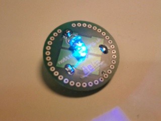
These are notes and files relating to the 'Learn To Solder' Robot Badge. This badge kit has been produced to use at events as a simple soldering exercise and promote the hackspace. This badge was based upon a simple flashing LED badge that was seen at UK Maker Faire 2011 in Newcastle. This robot shaped badge was designed by Matt Little based on an idea by Rob Keating from PCB manufacturers, Beta Layout. Beta Layout produced a number of batches of these PCBs for Nottingham Hackspace.
Build Instructions
Robot/Round Badge
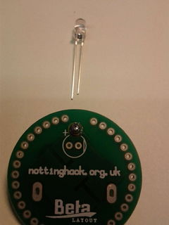
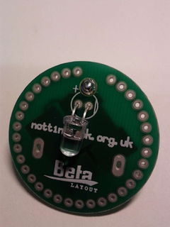
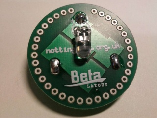
Solder the LED. Make sure the LED is the correct orientation. The long lead is positive and fits in the hole with the + symbol.
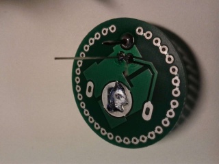
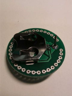
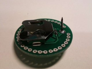
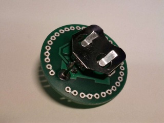
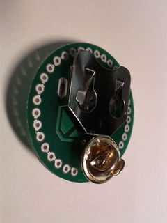
Push the battery clip into the back of the PCB. Make sure the open side is facing downwards so the battery can fit in.
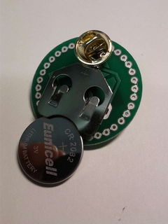
Push the battery in with the + side face up. And hopefully you should have a flashing badge...
.jpg)
.jpg)
.jpg)
.jpg)
.jpg)
.jpg)
.jpg)
.jpg)
.jpg)
.jpg)
.jpg)
.jpg)
.jpg)
.jpg)
.jpg)
.jpg)
.jpg)
SMD Robot Badge
.jpg)
.jpg)
.jpg)
.jpg)
.jpg)
.jpg)
.jpg)
.jpg)
.jpg)
.jpg)
.jpg)
.jpg)
.jpg)
.jpg)
.jpg)
.jpg)
.jpg)
.jpg)
.jpg)
.jpg)
.jpg)
.jpg)
.jpg)
.jpg)
.jpg)
.jpg)
Parts List - Simple
The simple version of the badge is just an LED wired derectly with a battery. A colour changing LED is used to make it a bit more interesting.
| Part | Details | Supplier |
| 3V Battery | CR2032 | eBay 1 Cost: £10 for 100
eBay 2 Cost: £10 for 100 |
| Battery clip | To hold above | Rapid: 18-3585 Cost: £0.312 100+
Farnell: 908654 Cost: £0.442 100+ Digikey UK: BK-888-ND Cost: £0.1674 100+ |
| LED | 5mm colour chaging | Rapid: 55-1906 £0.4326 100+
eBay 1: Cost: £6.99 for 30 eBay 2: Cost: £3.50 for 30 |
| Pin | 13mm panel pin | Stones hardware £0.56 for box (100pcs)
eBay 1 £1.60 for box |
| Badge Clip | To fit above pin | eBay 1: Cost: £4.99 for 100
eBay 2: Cost: £3 for 100 |
Parts List - SMD
The SMD version of the badge was designed for more advanced users so they can learn to do surface mount soldering or use an SMD oven. The circuit is a Flip Flop Two Transistor Flasher. The schematic diagram is here: ADD a PHOTO/PDF HERE
| Part | Reference | Details | Supplier |
| Capacitor | C1, C2 | Control flash rate. 10uf used. Size: 1206. | RS: 740-7546 |
| Resistor | R2, R3 | Control Flash Rate. 100k used. Size: 1206 | Rapid: 72-1437 |
| Resistor | R1, R4 | Limit LED current. 0 ohm with 3V battery. Size: 1206 | Rapid: 72-1207 |
| Transistor | Q1, Q2 | NPN type. S0323. BC817W used. | Farnell: 2114873 |
| LED | D3, D4 | Red or Green. Not enough voltage for Blue/White. Size: 1206 | Green. RS: 466 3908 |
PCB Files
The PCB was designed using KiCAD - an open source PCB design package.